Revision C: • The compressor winding resistance for MUZ-GE71VA - E1 has been changed. SPLIT-TYPE AIR CONDITIONERS Please void OBH516 REVISED EDITION-B. OUTDOOR UNIT SERVICE MANUAL HFC utilized No.
Revision A: • MUZ-GE42VA - E1 , MUZ-GE42VAH - E1 , MUZ-GE50VA - E1 and MUZ-GE50VAH - Revision B: • MUZ-GE60VA - E1 and MUZ-GE71VA - E1 have been added. Revision C: • The compressor winding resistance for MUZ-GE71VA - E1 has been changed. 2 E1 have been added.
1 TECHNICAL CHANGES MUZ-GE25VA - E1 MUZ-GE35VA - E1 MUZ-GE42VA - E1 MUZ-GE50VA - E1 MUZ-GE60VA - E1 MUZ-GE71VA - E1 MUZ-GE25VAH MUZ-GE35VAH MUZ-GE42VAH MUZ-GE50VAH - E1 - E1 - E1 - E1 1.
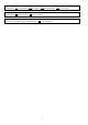
2 PART NAMES AND FUNCTIONS MUZ-GE25VA MUZ-GE25VAH MUZ-GE35VA MUZ-GE35VAH MUZ-GE42VA MUZ-GE42VAH Air inlet (back and side) Piping Drain hose Air outlet Drain outlet MUZ-GE50VA MUZ-GE50VAH Air inlet (back and side) Piping Drain hose Air outlet Drain outlet (GE50VA) MUZ-GE60VA MUZ-GE71VA Air inlet (back and side) Piping Drain hose Air outlet ACCESSORIES Model Drain socket Drain cap Drain outlet MUZ-GE25/35/42VA 1 - MUZ-GE50VA 1 2 4 MUZ-GE60/71VA 1 -
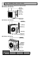
3 SPECIFICATION MUZGE35VA MUZGE35VAH MUZMUZGE42VA GE50VA MUZMUZOutdoor model MUZMUZGE60VA GE71VA GE42VAH GE50VAH Power supply Single phase, 230 V, 50 Hz 2.5 (1.1 - 3.5) 3.5 (1.1 - 4.0) 4.2 (0.9 - 4.8) 5.0 (1.4 - 5.5) 6.0 (1.5 - 7.5) 7.1 (2.4 - 8.7) Cooling Capacity kW Rated frequency (Min.-Max.) Heating 3.2 (1.3 - 4.5) 4.0 (1.6 - 5.3) 5.4 (1.4 - 6.0) 5.8 (1.4 - 7.3) 6.8 (2.0 - 9.3) 8.1 (2.2 - 9.
Specifications and rating conditions of main electric parts Model MUZMUZMUZMUZMUZMUZMUZMUZMUZMUZItem GE25VA GE25VAH GE35VA GE35VAH GE42VA GE42VAH GE50VA GE50VAH GE60VA GE71VA Current (CT) 20 A — transformer (C61, C62, C63) 620 μF 420 V — Smoothing capacitor (CB1, CB2, CB3) — 560 μF 450 V (DB61) 15 A 600 V 25 A 600 V — Diode module (DB65) 25 A 600 V — (F62) — T2.0AL250 V (F61) T20AL250V — Fuse (F701, F801, F901) T3.15AL250V — (F601, F880, F901) — T3.
4 NOISE CRITERIA CURVES MUZ-GE35VA MUZ-GE35VAH FUNCTION SPL(dB(A)) FUNCTION SPL(dB(A)) COOLING 47 COOLING 47 HEATING 48 HEATING 48 LINE 80 70 NC-70 60 NC-60 50 NC-50 40 NC-40 30 NC-30 20 NC-20 NC-10 10 80 70 NC-70 60 NC-60 50 NC-50 40 NC-40 30 NC-30 20 10 63 125 250 500 1000 2000 4000 8000 63 125 250 500 1000 2000 4000 8000 BAND CENTER FREQUENCIES, Hz MUZ-GE50VA MUZ-GE50VAH MUZ-GE42VA MUZ-GE42VAH FUNCTION SPL(dB(A)) FUNCTION SPL(dB(A)) COOLING 50 COOLING
MUZ-GE71VA FUNCTION SPL(dB(A)) FUNCTION SPL(dB(A)) COOLING 55 COOLING 55 HEATING 55 HEATING 55 LINE 90 80 70 NC-70 60 NC-60 50 NC-50 40 NC-40 30 NC-30 20 NC-20 NC-10 10 63 125 250 500 1000 2000 4000 8000 OCTAVE BAND SOUND PRESSURE LEVEL, 0dB re 0.0002 MICRO BAR OCTAVE BAND SOUND PRESSURE LEVEL, 0dB re 0.
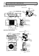
5 OUTLINES AND DIMENSIONS MUZ-GE25VA MUZ-GE25VAH MUZ-GE35VA MUZ-GE35VAH MUZ-GE42VA MUZ-GE42VAH Unit: mm REQUIRED SPACE 100 mm or more re Drain hole ø42 (MUZ-GE25/35/42VA) Drain hole ø33 (MUZ-GE25/35/42VAH) Bolt pitch for installation 304~325 44 285 344.5 400 Air in Air in o or m mm 0 0 1 100 mm or m ore 350 m ore 200 mm or more 17.5 40 2 holes 10 X 21 Service panel Air out 23 22.3 Liquid refrigerant pipe joint Refrigerant pipe (flared) ø6.
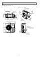
MUZ-GE60VA MUZ-GE71VA Unit: mm REQUIRED SPACE 500 mm or more 417.5 Drain hole 40 42 360 50 330 Air in 100 mm or more 100 mm or m ore Air out 2-holes 10 21 175 350 mm or m 500 500 mm or more 840 ore 81 109 Service panel 880 Liquid refrigerant pipe joint Refrigerant pipe (flared) Ø 6.35 (MUZ-GE60VA) Ø 9.52 (MUZ-GE71VA) 164.5 99.5 44 452 35 195 10 Gas refrigerant pipe joint Refrigerant pipe (flared) Ø 15.
6 WIRING DIAGRAM MUZ-GE25VA MUZ-GE35VA 11
MUZ-GE25VAH MUZ-GE35VAH 12
MUZ-GE42VA 13
MUZ-GE42VAH 14
MUZ-GE50VA 15
MUZ-GE50VAH 16
MUZ-GE60VA MUZ-GE71VA 17
7 REFRIGERANT SYSTEM DIAGRAM MUZ-GE25VA MUZ-GE25VAH Unit: mm Refrigerant pipe ø9.52 (with heat insulator) 4-way valve Muffler Stop valve (with service port) Discharge temperature thermistor RT62 Flared connection Outdoor heat exchanger Muffler Outdoor heat exchanger temperature thermistor RT68 Ambient temperature thermistor RT65 Compressor Defrost thermistor RT61 Strainer #100 Flared connection Capillary tube ø3.0×ø2.0×240 Refrigerant pipe ø6.35 (with heat insulator) LEV R.V.
MUZ-GE50VA MUZ-GE50VAH Unit: mm Muffler 4-way valve #100 Refrigerant pipe ø12.7 (with heat insulator) Stop valve (with service port) Flared connection Outdoor heat exchanger Discharge temperature thermistor RT62 Defrost thermistor RT61 Ambient temperature thermistor RT65 Compressor Outdoor heat exchanger temperature thermistor RT68 Flared connection LEV Receiver Refrigerant pipe ø6.35 (with heat insulator) Stop valve (with strainar) Strainer #100 R.V.
MUZ-GE71VA Unit: mm Muffler 4-way valve #100 Refrigerant pipe ø15.88 (with heat insulator) Stop valve (with service port) Flared connection Outdoor heat exchanger Discharge temperature thermistor RT62 Defrost thermistor RT61 Ambient temperature thermistor RT65 Compressor Outdoor heat exchanger temperature thermistor RT68 Flared connection LEV Strainer #100 Stop valve Strainer #100 R.V. coil heating ON cooling OFF Capillary tube ø4.0×ø2.
8 PERFORMANCE CURVES MUZ-GE25VA MUZ-GE25VAH MUZ-GE35VA MUZ-GE35VAH MUZ-GE42VA MUZ-GE42VAH MUZ-GE50VA MUZ-GE50VAH MUZ-GE60VA MUZ-GE71VA The standard specifications apply only to the operation of the air conditioner under normal conditions. Since operating conditions vary according to the areas where these units are installed, the following information has been provided to clarify the operating characteristics of the air conditioner under the conditions indicated by the performance curve.
8.2 5.1 6.5 8.0 7.9 7.2 7.5 4.6 5.9 7.2 7.1 6.5 6.8 4.2 5.3 6.5 6.4 5.8 6.1 3.7 4.7 5.7 5.7 5.2 5.4 3.3 4.1 5.0 5.0 4.6 4.7 MUZ-GE42VA MUZ-GE42VAH MUZ-GE50VA MUZ-GE50VAH 1.3 Input correction factors 7.9 1.2 1.0 0.9 Indoor intake air Wet-bulb temperature( ) 0.8 -5 0 5 10 15 20 25 30 35 40 Outdoor intake air Dry-bulb temperature (°C) 27.0 26.2 19.9 25.3 1.3 16.8 21.0 24.9 24.1 18.4 23.4 1.2 15.4 19.2 22.8 22.1 16.9 21.4 14.0 17.5 20.7 20.
8-2. CAPACITY AND INPUT CORRECTION BY OPERATIONAL FREQUENCY OF COMPRESSOR 0.5 2.0 1.0 0.0 0.0 0 50 The operational frequency of compressor (Hz) Correction of Heating capacity 1.5 Input correction factors 1.0 Correction of Cooling input 3.0 Capacity correction factors 1.5 Input correction factors Capacity correction factors MUZ-GE25VA MUZ-GE25VAH Correction of Cooling capacity 1.0 0.5 0.0 100 0 Correction of Heating input 2.0 1.5 1.0 0.5 0.
MUZ-GE60VA 2.0 Input correction factors Capacity correction factors Correction of Cooling input 1.5 1.5 1.0 1.0 0.5 0.5 0.0 0 50 100 150 The operational frequency of compressor (Hz) 0.0 0 2.0 1.5 1.5 1.0 1.0 0.5 0.5 0.0 0 50 100 150 The operational frequency of compressor (Hz) Correction of Heating input Correction of Heating capacity Capacity correction factors 2.0 2.0 Capacity correction factors Correction of Cooling capacity 0.
(kgf/cm2 [Gauge])(MPa [Gauge]) 0.7 7 6 5 4 3 (kgf/cm2 [Gauge])(MPa [Gauge]) 0.8 8 0.6 0.5 20 25 30 35 50 60 70 Ambient temperature(°C) Ambient humidity(%) (kgf/cm2 [Gauge])(MPa [Gauge]) 0.8 8 7 0.7 7 0.7 6 0.6 6 0.6 5 0.5 5 0.5 4 0.4 4 0.4 3 0.3 15 3 0.3 15 0.4 0.
HEAT operation Condition: Dry bulb temperature (°C) Wet bulb temperature (°C) Indoor 20.0 14.5 2 1 Outdoor 7 15 6 12 20.0 14.5 Operation: Test run operation (Refer to 8-3.) MUZ-GE35VA MUZ-GE35VAH 3.8 2.4 3.6 2.3 2.2 2.1 0 MUZ-GE50VA MUZ-GE50VAH 3.2 3.0 0 Outdoor current (A) 4.5 4.0 0 5 10 15 20 25 Ambient temperature (°C) 4.5 5 10 15 20 Ambient temperature(°C) 25 12 5.0 4.5 4.0 3.5 3.0 0 5.0 MUZ-GE71VA 5.5 5.0 5.5 4.0 5 10 15 20 25 Ambient temperature (°C) MUZ-GE60VA 5.
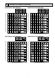
PERFORMANCE DATA COOL operation at Rated frequency MUZ-GE25VA MUZ-GE25VAH CAPACITY: 2.5 kW SHF: 0.96 INPUT: 545 W OUTDOOR DB (°C) INDOOR INDOOR DB (°C) WB (°C) 21 25 27 30 SHF INPUT 21 18 2.94 2.29 0.78 436 2.81 2.19 0.78 458 2.70 2.11 0.78 480 2.60 2.03 0.78 501 21 20 3.06 2.02 0.66 458 2.94 1.94 0.66 485 2.85 1.88 0.66 496 2.75 1.82 0.66 518 22 18 2.94 2.41 0.82 436 2.81 2.31 0.82 458 2.70 2.21 0.82 480 2.60 2.13 0.82 501 22 20 3.06 2.
PERFORMANCE DATA COOL operation at Rated frequency MUZ-GE25VA MUZ-GE25VAH CAPACITY: 2.5 kW SHF: 0.96 INPUT: 545 W OUTDOOR DB (°C) INDOOR INDOOR DB (°C) WB (°C) 35 40 46 SHF INPUT 21 18 2.45 1.91 0.78 534 2.25 1.76 0.78 567 2.08 1.62 0.78 589 21 20 2.58 1.70 0.66 556 2.40 1.58 0.66 583 2.23 1.47 0.66 616 22 18 2.45 2.01 0.82 534 2.25 1.85 0.82 567 2.08 1.70 0.82 589 22 20 2.58 1.80 0.70 556 2.40 1.68 0.70 583 2.23 1.56 0.70 616 22 22 2.73 1.
PERFORMANCE DATA COOL operation at Rated frequency MUZ-GE35VA MUZ-GE35VAH CAPACITY: 3.5 kW SHF: 0.82 INPUT: 865 W OUTDOOR DB (°C) INDOOR INDOOR DB (°C) WB (°C) 21 25 27 30 SHF INPUT 21 18 4.11 2.63 0.64 692 3.94 2.52 0.64 727 3.78 2.42 0.64 761 3.64 2.33 0.64 796 21 20 4.29 2.23 0.52 727 4.11 2.14 0.52 770 3.99 2.07 0.52 787 3.85 2.00 0.52 822 22 18 4.11 2.80 0.68 692 3.94 2.68 0.68 727 3.78 2.57 0.68 761 3.64 2.48 0.68 796 22 20 4.29 2.
PERFORMANCE DATA COOL operation at Rated frequency MUZ-GE35VA MUZ-GE35VAH CAPACITY: 3.5 kW SHF: 0.82 INPUT: 865 W OUTDOOR DB (°C) INDOOR INDOOR DB (°C) WB (°C) 35 40 46 SHF INPUT 21 18 3.43 2.20 0.64 848 3.15 2.02 0.64 900 2.91 1.86 0.64 934 21 20 3.61 1.87 0.52 882 3.36 1.75 0.52 926 3.12 1.62 0.52 977 22 18 3.43 2.33 0.68 848 3.15 2.14 0.68 900 2.91 1.98 0.68 934 22 20 3.61 2.02 0.56 882 3.36 1.88 0.56 926 3.12 1.74 0.56 977 22 22 3.82 1.
PERFORMANCE DATA COOL operation at Rated frequency MUZ-GE42VA MUZ-GE42VAH CAPACITY: 4.2 kW SHF: 0.77 INPUT: 1215 W OUTDOOR DB (°C) INDOOR INDOOR DB (°C) WB (°C) 21 25 27 30 Q SHC SHF INPUT Q SHC SHF INPUT Q SHC SHF INPUT Q SHC SHF INPUT 21 18 4.94 2.91 0.59 972 4.73 2.79 0.59 1021 4.54 2.68 0.59 1069 4.37 2.58 0.59 1118 21 20 5.15 2.42 0.47 1021 4.94 2.32 0.47 1081 4.79 2.25 0.47 1106 4.62 2.17 0.47 1154 22 18 4.94 3.11 0.63 972 4.73 2.
PERFORMANCE DATA COOL operation at Rated frequency MUZ-GE42VA MUZ-GE42VAH CAPACITY: 4.2 kW SHF: 0.77 INPUT: 1215 W OUTDOOR DB (°C) INDOOR INDOOR DB (°C) WB (°C) 35 40 46 Q SHC SHF INPUT Q SHC SHF INPUT Q SHC SHF INPUT 21 18 4.12 2.43 0.59 1191 3.78 2.23 0.59 1264 3.49 2.06 0.59 1312 21 20 4.33 2.03 0.47 1239 4.03 1.90 0.47 1300 3.74 1.76 0.47 1373 22 18 4.12 2.59 0.63 1191 3.78 2.38 0.63 1264 3.49 2.20 0.63 1312 22 20 4.33 2.21 0.51 1239 4.
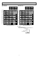
PERFORMANCE DATA COOL operation at Rated frequency MUZ-GE50VA MUZ-GE50VAH CAPACITY: 5.0 kW SHF: 0.76 INPUT: 1515 W OUTDOOR DB (°C) INDOOR INDOOR DB (°C) WB (°C) 21 25 27 30 SHF INPUT 21 18 5.88 3.41 0.58 1212 5.63 3.26 0.58 1273 5.40 3.13 0.58 1333 5.20 3.02 0.58 1394 21 20 6.13 2.82 0.46 1273 5.88 2.70 0.46 1348 5.70 2.62 0.46 1379 5.50 2.53 0.46 1439 22 18 5.88 3.64 0.62 1212 5.63 3.49 0.62 1273 5.40 3.35 0.62 1333 5.20 3.22 0.
PERFORMANCE DATA COOL operation at Rated frequency MUZ-GE50VA MUZ-GE50VAH CAPACITY: 5.0 kW SHF: 0.76 INPUT: 1515 W OUTDOOR DB (°C) INDOOR INDOOR DB (°C) WB (°C) 35 40 46 SHF INPUT 21 18 4.90 2.84 0.58 1485 4.50 2.61 0.58 1576 4.15 2.41 0.58 1636 21 20 5.15 2.37 0.46 1545 4.80 2.21 0.46 1621 4.45 2.05 0.46 1712 22 18 4.90 3.04 0.62 1485 4.50 2.79 0.62 1576 4.15 2.57 0.62 1636 22 20 5.15 2.58 0.50 1545 4.80 2.40 0.50 1621 4.45 2.23 0.
PERFORMANCE DATA COOL operation at Rated frequency MUZ-GE60VA CAPACITY: 6.0 kW SHF: 0.79 INPUT: 1760 W OUTDOOR DB (°C) INDOOR INDOOR DB (°C) WB (°C) 21 25 27 30 SHF INPUT 21 18 7.05 4.30 0.61 1408 6.75 4.12 0.61 1478 6.48 3.95 0.61 1549 6.24 3.81 0.61 1619 21 20 7.35 3.60 0.49 1478 7.05 3.45 0.49 1566 6.84 3.35 0.49 1602 6.60 3.23 0.49 1672 22 18 7.05 4.58 0.65 1408 6.75 4.39 0.65 1478 6.48 4.21 0.65 1549 6.24 4.06 0.65 1619 22 20 7.35 3.
PERFORMANCE DATA COOL operation at Rated frequency MUZ-GE60VA CAPACITY: 6.0 kW SHF: 0.79 INPUT: 1760 W OUTDOOR DB (°C) INDOOR INDOOR DB (°C) WB (°C) 35 40 46 21 18 Q 5.88 21 20 6.18 3.03 0.49 1795 5.76 2.82 0.49 1883 5.34 2.62 0.49 1989 22 18 5.88 3.82 0.65 1725 5.40 3.51 0.65 1830 4.98 3.24 0.65 1901 22 20 6.18 3.28 0.53 1795 5.76 3.05 0.53 1883 5.34 2.83 0.53 1989 22 22 6.54 2.68 0.41 1866 6.12 2.51 0.41 1971 5.70 2.34 0.41 2042 23 18 5.
PERFORMANCE DATA COOL operation at Rated frequency MUZ-GE71VA CAPACITY: 7.1 kW SHF: 0.78 INPUT: 2130 W OUTDOOR DB (°C) INDOOR INDOOR DB (°C) WB (°C) 21 25 27 30 SHF INPUT 21 18 8.34 5.01 0.60 1704 7.99 4.79 0.60 1789 7.67 4.60 0.60 1874 7.38 4.43 0.60 1960 21 20 8.70 4.17 0.48 1789 8.34 4.00 0.48 1896 8.09 3.89 0.48 1938 7.81 3.75 0.48 2024 22 18 8.34 5.34 0.64 1704 7.99 5.11 0.64 1789 7.67 4.91 0.64 1874 7.38 4.73 0.64 1960 22 20 8.70 4.
PERFORMANCE DATA COOL operation at Rated frequency MUZ-GE71VA CAPACITY: 7.1 kW SHF: 0.78 INPUT: 2130 W OUTDOOR DB (°C) INDOOR INDOOR DB (°C) WB (°C) 35 40 46 SHF INPUT 21 18 6.96 4.17 0.60 2087 6.39 3.83 0.60 2215 5.89 3.54 0.60 2300 21 20 7.31 3.51 0.48 2173 6.82 3.27 0.48 2279 6.32 3.03 0.48 2407 22 18 6.96 4.45 0.64 2087 6.39 4.09 0.64 2215 5.89 3.77 0.64 2300 22 20 7.31 3.80 0.52 2173 6.82 3.54 0.52 2279 6.32 3.29 0.52 2407 22 22 7.
PERFORMANCE DATA HEAT operation at Rated frequency MUZ-GE25VA MUZ-GE25VAH CAPACITY: 3.2 kW INPUT: 700 W OUTDOOR WB (°C) INDOOR DB (°C) -10 -5 0 5 10 15 20 Q INPUT Q INPUT Q INPUT Q INPUT Q INPUT Q INPUT Q INPUT 15 2.02 455 2.43 546 2.85 616 3.26 665 3.68 707 4.06 728 4.48 742 21 1.92 490 2.30 581 2.72 644 3.10 693 3.52 728 3.90 749 4.30 777 26 1.73 525 2.14 616 2.53 679 2.94 728 3.36 763 3.74 784 4.
9 ACTUATOR CONTROL MUZ-GE25VA MUZ-GE25VAH MUZ-GE35VA MUZ-GE35VAH MUZ-GE42VA MUZ-GE42VAH MUZ-GE50VA MUZ-GE50VAH MUZ-GE60VA MUZ-GE71VA 9-1. OUTDOOR FAN MOTOR CONTROL The fan motor turns ON/OFF, interlocking with the compressor. [ON] The fan motor turns ON 5 seconds before the compressor starts up. [OFF] The fan motor turns OFF 15 seconds after the compressor has stopped running. 5 seconds 15 seconds ON Compressor OFF ON Outdoor fan motor OFF 9-2. R.V. COIL CONTROL Heating . . . . . . . . . . . . . . . .
10 SERVICE FUNCTIONS MUZ-GE25VA MUZ-GE25VAH MUZ-GE35VA MUZ-GE35VAH MUZ-GE42VA MUZ-GE42VAH MUZ-GE50VA MUZ-GE50VAH MUZ-GE60VA MUZ-GE71VA 10-1. CHANGE IN DEFROST SETTING Changing defrost finish temperature To change the defrost finish temperature, cut/solder the JS wire of the outdoor inverter P.C. board. (Refer to 11-6-1.) Defrost finish temperature (°C) MUZ-GE25/35/42 MUZ-GE50 MUZ-GE60/71 5 9 10 10 18 18 Jumper wire JS Soldered (Initial setting) None (Cut) 10-2.
11-2. FAILURE MODE RECALL FUNCTION Outline of the function This air conditioner can memorize the abnormal condition which has occurred once. Even though LED indication listed on the troubleshooting check table (11-3.) disappears, the memorized failure details can be recalled. 1.
2. Flow chart of the detailed outdoor unit failure mode recall function Operational procedure The outdoor unit might be abnormal. Confirm if outdoor unit is abnormal according to the following procedures. Confirm that the remote controller is in the failure mode recall function. With the remote controller headed towards the indoor unit, press TOO COOL or TOO WARM button (MSZ-GE25/35/42/50VA)/TEMP button (MSZGE60/71VA) to adjust the set temperature to 25°C.
3. Outdoor unit failure mode table The upper lamp of OPERATION Abnormal point INDICATOR (Failure mode / protection) lamp (Indoor unit) OFF None (Normal) LED indication (Outdoor P.C. board) Condition Correspondence — — — — Overcurrent protection stop is continuously performed 3 times within 1 minute after the compressor gets started. • Reconnect connectors. • Refer to 11-5. "How to check inverter/ compressor". • Check stop valve. • Refer to 11-5. "Check of outdoor thermistors".
11-3. TROUBLESHOOTING CHECK TABLE No. 1 Symptom Outdoor unit does not operate. Abnormal point/ Condition 1-time flash every Outdoor power sys2.5 seconds tem LED indication 2 3 6-time flash 2.5 seconds OFF 11-time flash 2.5 seconds OFF 14-time flash 2.5 seconds OFF 4 5 6 7 8 'Outdoor unit 2-time flash stops and 2.5 seconds OFF restarts 3 minutes later' is repeated. 3-time flash 2.5 seconds OFF 4-time flash 2.
11-4. TROUBLE CRITERION OF MAIN PARTS MUZ-GE25VA MUZ-GE25VAH MUZ-GE35VA MUZ-GE35VAH MUZ-GE42VA MUZ-GE42VAH MUZ-GE50VA MUZ-GE50VAH MUZ-GE60VA MUZ-GE71VA Part name Defrost thermistor (RT61) Fin temperature thermistor (RT64) Ambient temperature thermistor (RT65) Check method and criterion Figure Measure the resistance with a tester. Refer to 11-6. “Test point diagram and voltage”, 1. “Inverter P.C. board”, for the chart of thermistor.
11-5. TROUBLESHOOTING FLOW A How to check inverter/compressor Disconnect the connector between compressor and the intelligent power module (IPM). See 11-5. Check the voltage between terminals. Are the voltages balanced? Yes No Replace the inverter P.C. board. See 11-5. Check the compressor. “Check of open phase”. “Check of compressor”.
D Check of compressor winding ●Disconnect the connector between the compressor and intelligent power module, and measure the resistance between the compressor terminals. <> at 3 points BLK-WHT Measure the resistance between the lead wires at 3 points. BLK-RED WHT-RED <> Refer to 11-4. 0 [Ω] ················Abnormal [short] Infinite [Ω] ·······Abnormal [open] NOTE: Be sure to zero the ohmmeter before measurement.
G Check of outdoor thermistors Disconnect the connector of thermistor in the outdoor P.C. board (see below table), and measure the resistance of thermistor. Is the resistance of thermistor normal? (Refer to 11-6.1.) Yes No Replace the thermistor except RT64. When RT64 is abnormal, replace the inverter P.C. board. Reconnect the connector of thermistor. Turn ON the power supply and press EMERGENCY OPERATION switch.
I Check of outdoor fan motor MUZ-GE25VA MUZ-GE25VAH MUZ-GE35VA MUZ-GE35VAH MUZ-GE42VA MUZ-GE42VAH Disconnect CN932 from the inverter P.C. board, and measure the resistance of the outdoor fan motor. Is the resistance of outdoor fan motor normal? (Refer to 11-4.) Yes Replace the outdoor fan motor. No Replace the inverter P.C. board. MUZ-GE50VA MUZ-GE50VAH MUZ-GE60VA MUZ-GE71VA Disconnect the connectors CN931 and CN932 from the inverter P.C. board.
J Check of power supply MUZ-GE25VA MUZ-GE25VAH MUZ-GE35VA MUZ-GE35VAH MUZ-GE42VA MUZ-GE42VAH MUZ-GE50VA MUZ-GE50VAH Disconnect the connector between compressor and intelligent power module. Turn ON power supply and press EMERGENCY OPERATION switch. Rectify indoor/outdoor connecting wire. Does The upper lamp of OPERATION INDICATOR lamp on the indoor unit light up? Yes No Is there voltage 280 - 370 VDC between DB61 (+) and DB61 (–) on the inverter P.C. board? (Refer to 11-6.1.
K Check of LEV (Expansion valve) Turn ON the power supply. While pressing both OPERATION SELECT button and TOO COOL button (MSZ-GE25/35/42/50VA)/ TEMP button (MSZ-GE60/71VA) on the remote controller at the same time, press RESET button. First, release RESET button. And release the other two buttons after all LCD except the set temperature in operation display section of the remote controller is displayed after 3 seconds.
L Check of inverter P.C. board Check the outdoor fan motor. (Refer to 11-5. .) Is the fuse (F901) blown on the inverter P.C. board? Yes No Check the connection of the connectors (CN931 , CN932) of the outdoor fan motor. If the connection is poor, make it correct. MUZ-GE50/60/71 Operate the outdoor unit by starting EMERGENCY OPERATION. Check the LED indication on the inverter P.C. board. Does the LED flash 10 times? Yes (10-time flash) No Check the corresponding parts following LED indication.
M How to check miswiring and serial signal error MUZ-GE25VA MUZ-GE25VAH MUZ-GE35VA MUZ-GE35VAH MUZ-GE42VA MUZ-GE42VAH MUZ-GE50VA MUZ-GE50VAH Turn OFF the power supply. Is there rated voltage in the power supply? Yes Check the power supply. No Turn ON the power supply. Is there rated voltage between outdoor terminal block S1 and S2? Yes No Check the wiring. Press EMERGENCY OPERATION switch once.
MUZ-GE60VA MUZ-GE71VA Turn OFF the power supply. Is there rated voltage in the power supply? Yes Check the power supply. No Turn ON the power supply. Is there rated voltage between outdoor terminal block S1 and S2? Yes No Check the wiring. Press EMERGENCY OPERATION switch once. Does the upper lamp of OPERATION INDICATOR lamp light up? Yes Is serial signal error indicated 6 minutes later? Yes A Turn OFF the power supply.
N Electromagnetic noise enters into TV sets or radios Is the unit earthed? Yes Is the distance between the antennas and the indoor unit within 3 m, or is the distance between the antennas and the outdoor unit within 3 m? No Earth the unit. No Yes Extend the distance between the antennas and the indoor unit, and/or the antennas and the outdoor unit.
O Check of defrost heater MUZ-GE•VAH Check the following points before checking electric continuity. 1. Does the resistance of ambient temperature thermistor have the characteristics? Refer to 11-6.1. 2. Is the resistance of defrost heater normal? Refer to 11-4. 3. Does the heater protector remain conducted (not open)? 4.
11-6. TEST POINT DIAGRAM AND VOLTAGE 1. Inverter P.C. board MUZ-GE25VA MUZ-GE25VAH MUZ-GE35VA MUZ-GE35VAH MUZ-GE42VA MUZ-GE42VAH DB61 280 - 370 VDC (-) (+) Back side of unit Smoothing capacitor (C62) Smoothing capacitor (C63) Smoothing capacitor (C61) Fuse (F701) T3.15AL250V Fuse (F801) T3.15AL250V 230 VAC Heater connector (CN722) MUZ-GE•VAH R.V.coil (CN721) 230 VAC Fuse (F901) T3.
MUZ-GE50VA MUZ-GE50VAH Back side of unit Smoothing capacitor (C62) Smoothing capacitor (C63) DB61 280 - 370 VDC (-) (+) Smoothing R.V.coil capacitor Fuse (F701) (CN721) (C61) T3.15AL250V 230 VAC Fuse (F801) T3.15AL250V 230 VAC Heater connector (CN722) MUZ-GE•VAH Fuse (F901) T3.
MUZ-GE60VA MUZ-GE71VA Fuse (F62) T2.0AL250V R.V. coil (CN602) 230VAC Fuse (F601) T3.15AL250V Jumper wire for changing defrost setting (JS) Jumper wire for pre-heat control setting (JK) Signal of outdoor fan motor (CN931) Defrost thermistor /RT61 (CN671) Discharge temperature thermistor/RT62 (CN671) Outdoor heat exchanger temperature thermistor /RT68 (CN671) Ambient temperature thermistor/RT65 (CN672) Fin temperature thermistor/RT64 (CN673) LED Output to drive outdoor fan motor (CN932) Fuse (F901) T3.
12 DISASSEMBLY INSTRUCTIONS <"Terminal with locking mechanism" Detaching points> The terminal which has the locking mechanism can be detached as shown below. There are two types (refer to (1) and (2)) of the terminal with locking mechanism. The terminal without locking mechanism can be detached by pulling it out. Check the shape of the terminal before detaching. (1) Slide the sleeve and check if there is a locking lever or not. (2) The terminal with this connector has the locking mechanism.
OPERATING PROCEDURE PHOTOS 2. Removing the inverter assembly, inverter P.C. board Photo 3 (1) Remove the cabinet and panels. (Refer to 1.) (2) Disconnect the lead wire to the reactor and the following connectors: CN721 (R.V. coil) CN722 (Defrost heater) CN932 (Fan motor) CN641 (Defrost thermistor and discharge temperature thermistor) CN643 (Ambient temperature thermistor) CN644 (Outdoor heat exchanger temperature thermistor) CN724 (LEV) (3) Remove the compressor connector (CN61).
OPERATING PROCEDURE PHOTOS 5. Removing outdoor fan motor Photo 6 (1) Remove the cabinet and panels. (Refer to 1.) (2) Disconnect the following connectors: CN932 (Fan motor) (3) Remove the propeller nut. (Photo 7) (4) Remove the propeller. (Photo 7) (5) Remove the screws fixing the fan motor. (Photo 7) (6) Remove the fan motor. Outdoor heat exchanger temperature thermistor 6. Removing the compressor and 4-way valve (1) Remove the cabinet and panels. (Refer to 1.
12-2. MUZ-GE50VA MUZ-GE50VAH NOTE: Turn OFF power supply before disassembling. OPERATING PROCEDURE PHOTOS 1. Removing the cabinet Photo 1 (1) (2) (3) (4) (5) (6) (7) Remove the screws of the service panel. Remove the screws of the top panel. Remove the screw of the valve cover. Remove the service panel. Remove the top panel. Remove the valve cover. Disconnect the power supply and indoor/outdoor connecting wire. (8) Remove the screws of the cabinet. (9) Remove the cabinet.
OPERATING PROCEDURE PHOTOS 2. Removing the inverter assembly, inverter P.C. board Photo 3 Screws of the relay panel (1) Remove the cabinet and panels. (Refer to 1.) (2) Disconnect the lead wire to the reactor and the following connectors: CN721 (R.V.
OPERATING PROCEDURE PHOTOS 4. Removing the discharge temperature thermistor, defrost thermistor, outdoor heat exchanger temperature thermistor and ambient temperature thermistor Photo 6 Outdoor heat exchanger temperature thermistor (1) Remove the cabinet and panels. (Refer to 1.) (2) Disconnect the lead wire to the reactor and the following connectors:
12-3. MUZ-GE60VA MUZ-GE71VA NOTE: Turn OFF power supply before disassembling. OPERATING PROCEDURE PHOTOS 1. Removing the cabinet Photo 1 (1) (2) (3) (4) (5) (6) (7) Remove the screws of the service panel. Remove the screws of the top panel. Remove the screw of the valve cover. Remove the service panel. Remove the top panel. Remove the valve cover. Disconnect the power supply and indoor/outdoor connecting wire. (8) Remove the screws of the cabinet. (9) Remove the cabinet.
OPERATING PROCEDURE PHOTOS 2. Removing the inverter assembly, inverter P.C. board (1) Remove the cabinet and panels. (Refer to 1.) (2) Disconnect the lead wire to the reactor and the following connectors: CN602 (R.V. coil) CN931, CN932 (Fan motor) CN671 (Defrost thermistor, discharge temperature thermistor and outdoor heat exchanger temperature thermistor) CN672 (Ambient temperature thermistor) CN724 (LEV) (3) Remove the compressor connector.
OPERATING PROCEDURE PHOTOS 4. Removing the discharge temperature thermistor, defrost thermistor, outdoor heat exchanger temperature thermistor and ambient temperature thermistor (1) Remove the cabinet and panels. (Refer to 1.) (2) Disconnect the lead wire to the reactor and the following connectors:
HEAD OFFICE: TOKYO BLDG., 2-7-3, MARUNOUCHI, CHIYODA-KU, TOKYO 100-8310, JAPAN © Copyright 2008 MITSUBISHI ELECTRIC CO.,LTD Distributed in Jun. 2010. No. OBH516 REVISED EDITION-C 5 Distributed in Oct. 2009. No. OBH516 REVISED EDITION-B 5 Distributed in Dec. 2008. No. OBH516 REVISED EDITION-A 5 Distributed in Aug. 2008. No. OBH516 6 Made in Japan New publication, effective Jun. 2010 Specifications subject to change without notice.