
Service manual

8
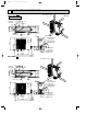
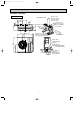
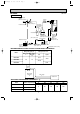
REFRIGERANT SYSTEM DIAGRAM6
MU-A24ND
OUTDOOR UNIT
Outdoor
heat
exchanger
Flared connection
Flared connection
Stop valve
Stop valve
(with service port)
Capillary tube
[3.0 x [2.0 x 550
Refrigerant flow in cooling
Compressor
Refrigerant pipe
[15.88
(with heat insulator)
Refrigerant pipe
[6.35
(with heat insulator)
Strainer
#100
Accumulator
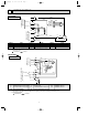
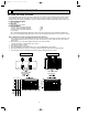
MU-A18ND
OUTDOOR UNIT
Unit : mm
Refrigerant pipe
{6.35
(with heat insulator)
Refrigerant pipe
{12.7
(with heat insulator)
Compressor
Outdoor heat
exchanger
Flared
connection
Strainer
#100
Stop Valve
(with service port)
Stop Valve
Capillary tube
[3.0 x [1.8 x 400
OB405E.qxp 09.10.14 9:16 AM Page 8