
Service manual

14
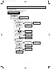
8-3. Trouble criterion of main parts
MU-A18ND MU-A24ND MU-A30ND
Part name FigureCheck method and criterion
Measure the resistance between the terminals with a tester.
(Coil wiring temperature -10°C ~ 40°C)
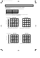
Compressor
(MC)
INNER
PROTECTOR
155i 5: OPEN
90i10: CLOSE
Normal
MU-A18ND
Color of
lead wire
C – R
C – S
1.26 " ~ 1.55 "
1.81 " ~ 2.23 "
MU-A24ND
0.74 " ~ 0.91 "
1.84 " ~ 2.26 "
MU-A30ND
0.54 " ~ 0.67 "
1.23 " ~ 1.52 "
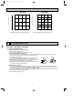
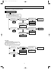
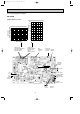
LEV(Expansion valve)
MU-A30ND
Color of lead wire
WHT – RED
RED – ORN
YLW – BRN
BRN – BLU
Normal
37.4 " ~ 53.9 "
Measure the resistance with a tester.
(Part temperature : 0˚C ~ 40˚C)
Measure the resistance with a tester.
(Part temperature –10˚C ~ 40˚C)
Discharge temperature
thermistor(RT62)
MU-A30ND
Ambient temperature
thermistor(RT63)
MU-A30ND
Measure the resistance with a tester.
Before measurement, hold the thermistor with your hands to warm it up.
(Part temperature 0˚C ~ 40˚C)
Refer to 8-5. "Test point diagram and voltage", "Outdoor deicer P.C. board",
the chart of thermistor.
Refer to 8-5. "Test point diagram and voltage", "Outdoor deicer P.C. board",
the chart of thermistor.
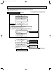
MU-A18ND MU-A24ND MU-A30ND
Measure the resistance between the terminals with a tester.
(Coil wiring temperature -10°C ~ 40°C)
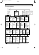
Color of
lead wire
WHT – BLK
BLK – RED
BLK – YLW
YLW – RED
63 " ~ 77 "
79 " ~ 96 "
–
–
57 " ~ 70 "
58 " ~ 71 "
–
–
57 " ~ 69 "
–
29 " ~ 35 "
29 " ~ 35 "
Normal
Outdoor fan motor
(MF)
INNER
PROTECTOR
135i 5: OPEN
87i15: CLOSE
Measure the resistance with a tester.
(Part temperature : –10˚C ~ 40˚C)
Solenoid valve coil
(21S2)
MU-A30ND
Normal
MU-A30ND -
S1
1,738 " ~ 2,125 "
MU-A30ND -
S2
1,230 " ~ 1,330 "
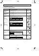
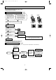
WHT
BLK YLW
RED
ORN
MAIN
AUX.
MAIN
AUX.
WHTBLK RED ORN
MU-A18/A24ND
MU-A30ND
RED
WHT
BLK
P
C
SR
:INNER PROTECTOR
P
LEV
WHT
6
RED1
ORN4
YLW5
BRN2
BLU3
OB405E.qxp 09.10.14 9:16 AM Page 14