
Service manual

8
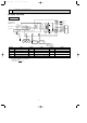
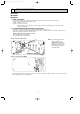
REFRIGERANT SYSTEM DIAGRAM
6
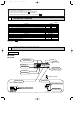
MS-A18ND
INDOOR UNIT
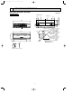
Unit : mm
Indoor
heat
exchanger
Flared connection
RT11
Room
temperature
thermistor
Distributor
Flared connection
Refrigerant pipe
[12.7
(with heat insulator)
Refrigerant pipe
[6.35
(with heat insulator)
Main indoor coil
thermistor
RT12
Strainer
#50
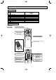
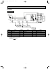
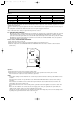
MS-A24ND
INDOOR UNIT
Indoor
heat
exchanger
Flared connection
Room temperature
thermistor
RT11
Flared connection
Refrigerant flow in cooling
Refrigerant pipe
[15.88
(with heat insulator)
Refrigerant pipe
[6.35
(with heat insulator)
Main indoor coil
thermistor
RT12
Strainer
#50
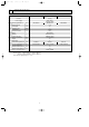
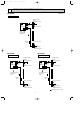
Indoor
heat
exchanger
Flared connection
Room temperature
thermistor
RT11
Sub indoor coil
thermistor
RT13
Flared connection
Refrigerant pipe
[15.88
(with heat insulator)
Refrigerant pipe
[9.52
(with heat insulator)
Main indoor coil
thermistor
RT12
Strainer
#50
MS-A30ND
INDOOR UNIT
OB404A--1.qxp 06.4.26 6:01 PM Page 8