
Service manual

18
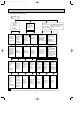
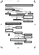
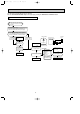
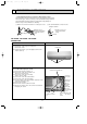
8-6. Test point diagram and voltage
MS-A18ND MS-A24ND MS-A30ND
Indoor electronic control P.C.board
Fan motor power supply
220-230V AC(CN211)
Fuse (F11)
250V AC 3.15A
}
Power supply input
220-230V AC
+
}
5V DC
Main indoor coil
thermistor(RT12)
Timer short mode point
(JPS, JPG)
(Refer to 7-1.)
Emergency operation
switch
+
}
12V DC
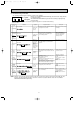
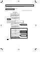
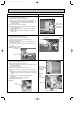
Main indoor coil thermistor (RT12)
Sub indoor coil thermistor (RT13)
Room temperature thermistor (RT11)
Temperature (:)
Resistance (k")
Room temperature
thermistor(RT11)
MS-A30ND
Sub indoor coil
thermistor(RT13)
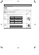
Release of Auto restart function
Solder the Jumper wire or the
Resistor 220" to the Resistor
JR07. (Refer to 7-3.)
Varistor (NR11)
CN121
Vane motor
power supply
(CN151)
CN301
PS132
MS-A30ND
OB404A--1.qxp 06.4.26 6:01 PM Page 18