
Service manual

14
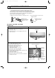
Room
temperature
thermistor
(RT11)
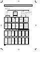
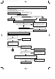
8-4. Trouble criterion of main parts
MS-A18ND
MS-A24ND
MS-A30ND
Part name
Indoor coil
thermistor
(RT12(main), RT13(sub))
Check method and criterion
Figure
Measure the resistance between the terminals with a tester.
(Coil wiring temperature10°C ~ 30°C)
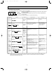
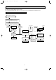
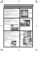
Indoor fan
motor (MF)
INNER
PROTECTOR
135i 5: OPEN
86i15: CLOSE
Motor part
Sensor part
Measure the voltage Power ON.
MAIN
AUX.
BLK
REDWHT
PP
:INNER PROTECTOR
Horizontal vane
motor(MV1)
Vertical vane
motor(MV2)
Measure the resistance between the RED terminals and other ones.
(Winding temperature10°C ~ 30°C)
ORN
BLUYLW
RED
PNK
ROTOR
Measure the resistance with a tester.
(Part temperature 10°C ~ 30°C)
Refer to 8-6. “Test point diagram and voltage”, “Indoor electronic control P.C.
board”, the chart of thermistor.
282 ~ 306 "
Normal
Color of lead wire
WHT - BLK
BLK - RED
Normal
132 ~ 144 "
152 ~ 166 "
Color of lead wire
BRN - YLW
YLW - GRY
Normal
4.5 ~ 5.5 V
(When fan revolved one time)
0V➔5V➔0V
(Approx.)
OB404A--1.qxp 06.4.26 6:01 PM Page 14