
Service manual

Indoor
unit
1
Refrigerant pipe
63/8
(Option)
Fl
(with heat insulator)
connection
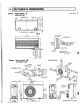
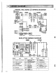
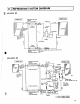
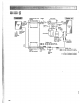
REFRIGERANT SYSTEM DIAGRAM
Room temd
I
I
$all valve
\
1
Accumulator
Fusible plug
-
efr,gerant
pipe
1 /4
Ball valve
Capillary tube
(60.1 2
x
(6
1 /16 x 47-1 /4
(Option)
with
senrice
(with heat insulator)
POrt
Refrigerant pipe
63/8
4-way
valve
(Option)
(with heat insulator)
--
Flared connection
thermistor
RTl
1
II
Compressor
(
I-
2-way
--..-
(Option)
(with
heat insulator)
polt)
40.12~1/16~35-7/16
R.V.
coil
heating ON
cooling OFF
Strainer
-
a low
of
refrigerant
iding)
---*
Flow of
refrigerant
(heating)