
Service manual


25
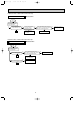
TEST POINT DIAGRAM AND VOLTAGE
MSC-07RV -
MSC-09RV -
MSC-12RV -
Indoor electronic control P.C. board
E4
E4
E4
Fan motor power supply
Fuse(F11) 250V AC 3.15A
}
Power supply input
220-240V AC
CN121
CN112
Indoor coil
thermistor (RT12)
Emergency operation switch
+
}
5V
DC
CN111
Room temperature
thermistor (RT11)
Resistance(k")
JPGND
J205
Timer short mode point
(JPS, JPG)
Vane motor power supply
(CN151)
}
Varistor (NR11)
CN201
SW2 (Refer to page 121 of
OB227 REVISED EDITION-B.)
1 sets the Auto restart function
ON/ OFF.
2 switches over MU and MUX
type/ MUH and MXZ type.
}
12V
DC
+
CN302
P.C.board
0~20V DC
R132
OB252C-1.qxp 02.4.25 11:28 AM Page 25