
Service manual


15
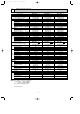
REFRIGERANT SYSTEM DIAGRAM
5
Unit:mm
MSC-12RV - MSC-12RV -
E4E3
MUH-12RV - MUH-12RV -
E4E3
INDOOR UNIT
OUTDOOR UNIT
(with heat insulator)
(with heat insulator)
Refrigerant pipe [12.7
4-way valve
Muffler
Stop valve
(with service port)
Strainer
Refrigerant pipe [6.35
Stop valve
Capillary tube
[3.0x[1.6x700
Check
valve
Refrigerant flow in cooling
Refrigerant flow in heating
Defrost
thermistor
RT61
Outdoor
heat
exchanger
Room temperature
thermistor
RT11
Indoor coil
thermistor
RT12
Capillary tube
[3.0x[1.8x300
Flared connection
Flared connection
Compressor
Indoor
heat
exchanger
R.V. coil
heating ON
cooling OFF
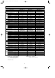
MSC-07RV - MSC-07RV -
MSC-09RV - MSC-09RV -
E4E3
E4E3
MUH-07RV - MUH-07RV -
MUH-09RV - MUH-09RV -
E4E3
E4E3
INDOOR UNIT
OUTDOOR UNIT
Indoor
heat
exchanger
Room temperature
thermistor
RT11
(with heat insulator)
Refrigerant pipe [ 9.52
Muffler
4-way valve
Defrost
thermistor
RT61
Strainer
Outdoor
heat
exchanger
Capillary tube
[3.0x[1.4x800 (2 pcs)
Capillary tube
[3.0x[1.6x600(MUH-07)
[3.0x[1.6x400(MUH-09)
Capillary tube
[3.0x[1.4x600(MUH-07)
[3.0x[1.4x550(MUH-09)
Check valve
Strainer
Refrigerant pipe [6.35
(with heat insulator)
Refrigerant flow in cooling
Refrigerant flow in heating
Unit:mm
Stop valve
(with service
port)
Indoor coil
thermistor
RT12
R.V. coil
heating ON
cooling OFF
Capillary tube
[3.0x[1.4x500(2pcs)
Flared connection
Flared connection
Compressor
Stop valve
Strainer
OB252C-1.qxp 02.4.25 11:27 AM Page 15