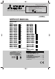
OB252C-1.qxp 02.4.25 11:27 AM Page 1 NOTE: • This service Manual covers only change points. Please refer to the Service Manual OB227 REVISED EDITION-B for unchanged contents. • Please refer to the following service manual when the outdoor unit is the under mentioned model. MXZ-32SV- E1 : OB254 MXZ-18TV- E1 : OB280 MUX-19/20/25TV- E1 : OB284 • Please void OB252 REVISED EDITION-B. SPLIT-TYPE, AIR CONDITIONERS SPLIT-TYPE, HEAT PUMP AIR CONDITION No.
OB252C-1.qxp 02.4.25 11:27 AM Page 2 REVISION Parts numbers have been partially modified.
OB252C-1.qxp 02.4.25 11:27 AM 1 Page 3 TECHNICAL CHANGES Circle shows the change point of the model. No. Change point 1 2 3 4 5 6 7 8 9 10 11 12 13 MSC-09RV- MSC-07RVE1 The specifications of Indoor and Outdoor fan motor. The data of Med. and Low speed are added to Indoor fan motor specification✼ ✼The data value of indoor fan motor does not change if the indoor unit is connected to a multi-type outdoor unit. Remote controllers of COOL ONLY or COOL & HEAT type are outdoor unit accessory.
OB252C-1.qxp 02.4.25 11:27 AM Page 4 Circle shows that change points apply to the models. No. Change point 1 Remote controller of COOL ONLY type is outdoor unit accessory. 2 Remote controller is included as an indoor unit accessory. 3 4 5 6 7 8 9 10 11 12 13 MU-09RV- MU-07RVE1 Compressor contactor (52C) has changed. Compressor contactor for E2,E3,E4 are interchangeable with the ones for E1. Compressor has changed. Compressors for E3 and E4 are not interchangeable with the ones for E1 and E2.
OB252C-1.qxp 02.4.25 11:27 AM Page 5 Circle shows that change points apply to the models. Change point No. 1 2 3 4 5 6 7 8 9 10 11 12 13 14 15 16 17 Remote controller of COOL & HEAT type is outdoor unit accessory. Remote controller is included as an indoor unit accessory. Accumulator has been removed. Compressor has changed. Compressor capacitor has changed. Due to different shape, compressor capacitor for E4 is not interchangeable with the ones for E1,E2 and E3.
OB252C-1.qxp 02.4.25 11:27 AM Page 6 Reference REMOTE CONTROLLER Model COOL ONLY COOL & HEAT TWO-WAY TWO-WAY DIP switch ✕ ✕ ✕ MS-07/09/12RV- E1 MSH-07/09/12RV- E1 ✕ w When HEAT mode is selected w MS-07/09/12RV- E2 MSH-07/09/12RVMS-07/09/12RV- E3 ✕ MSH-07/09/12RV- E3 ✕ E2 by the remote controller of COOL & HEAT type, the unit will operate in FAN mode.
OB252C-1.qxp 02.4.25 11:27 AM Page 7 • The way of remodelling individual operation of P.C Board of remote controller has changed. A maximum of 4 indoor units with wireless remote controllers can be used in a room. In this case, to operate each indoor unit individually by each remote controller, P.C. boards of remote controller must be modified according to the number of the indoor unit. How to modify the remote controller P.C. board Remove batteries before modification.
OB252C-1.qxp 02.4.25 11:27 AM Page 8 • How to replace batteries Weak batteries may cause the remote controller malfunction. In this case, replace the batteries to operate the remote controller normally. 1 Remove the front lid and insert batteries. Then re-attach the front lid. / 2 Press the RESET button. HE /FA AT N / HE /FA AT N Insert the negative pole of the batteries first. Check if the polarity of the batteries are correct.
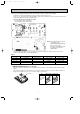
OB252C-1.qxp 02.4.25 11:27 AM Page 9 MSC-07RV - E2 MSC-09RV - E2 MSC-12RV - E2 REMOTE CONTROLLER Signal transmitting section Operation display section AM CLOCK PM 6 00 1 1 00 OPERATE /STOP (ON /OFF)button ON/OFF TOO WARM TOO COOL OPERATION SELECT button TEMPERATURE buttons MODE I FEEL COOL DRY HEAT/FAN VANE FAN VANE CONTROL button FAN SPEED CONTROL button ECONO COOL ECONO COOL button STOP START ON-TIMER button CLOCK SET button HR. button MIN.
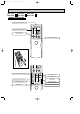
OB252C-1.qxp 02.4.25 11:27 AM Page 10 MSC-07RV - E3 MSC-09RV - E3 MSC-12RV - E3 MSC-07RV - E4 MSC-09RV - E4 MSC-12RV - E4 REMOTE CONTROLLER Signal transmitting section Operation display section PM AM OPERATE /STOP (ON /OFF)button TOO ON/OFF WARM TOO COOL TEMPERATURE buttons Open the front lid. CLOCK PM AM TOO ON/OFF WARM FAN SPEED CONTROL button TOO COOL FAN STOP VANE START I FEEL COOL HEAT /FAN OFF-TIMER button DRY ON-TIMER button / MODE HR. ECONO COOL MIN.
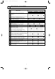
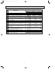
OB252C-1.qxp 02.4.25 11:27 AM 3 Page 11 SPECIFICATION Indoor model Function Indoor unit power supply Special remarks Fan motor Electrical data Capacity Air flow(High/Med.w/Low w ) Power outlet Running current Power input Power factor Starting current Fan motor current Model Winding resistance(at20:) Dimensions WOHOD Weight Air direction Sound level(High/Med.w/Loww ) Fan speed (High/Med.
OB252C-1.qxp 02.4.25 11:27 AM Page 12 Indoor model Function Indoor unit power supply Special remarks Fan motor Electrical data Capacity Air flow(High/Med.w/Low w) Power outlet Running current Power input Power factor Starting current Fan motor current Model Winding resistance(at20:) Dimensions WOHOD Weight Air direction Sound level(High/Med.w/Loww ) Fan speed(High/Med.
OB252C-1.qxp 02.4.25 11:27 AM 4 Page 13 WIRING DIAGRAM MSC-07RV - E4 MSC-09RV - E4 MSC-12RV - E4 MODELS WIRING DIAGRAM INDOOR UNIT TO OUTDOOR TB UNIT L CONNECTING BRN FOR 3 MUH OR MXZ TYPE N 12V FOR MU OR MUX TYPE 12V 2 BRN TAB12 RED CN201 3 2 1 CN202 2 1 BLU BLU WHT 1 BLK TRANS F11 RT12 CN 111 RT11 CN 121 C11 SR141 BLK GRY YLW BRN WHT RED 3 1 3 5 1 2 3 MF 4 5 6 CN211 ELECTRONIC CONTROL P.C.
OB252C-1.qxp 02.4.
OB252C-1.qxp 02.4.25 11:27 AM 5 Page 15 REFRIGERANT SYSTEM DIAGRAM Unit:mm MUH-07RV - E3 MUH-07RV - E4 MUH-09RV - E3 MUH-09RV - E4 MSC-07RV - E3 MSC-07RV - E4 MSC-09RV - E3 MSC-09RV - E4 INDOOR UNIT (with heat insulator) Indoor heat exchanger Indoor coil thermistor RT12 OUTDOOR UNIT Refrigerant pipe [ 9.52 Flared connection 4-way valve Muffler Defrost thermistor RT61 Stop valve (with service port) Outdoor heat exchanger Strainer Room temperature thermistor RT11 Capillary tube [3.0x[1.
OB252C-1.qxp 6 02.4.25 11:27 AM Page 16 MICROPROCESSOR CONTROL MSC-07RV - E4 MU-07RV - E4 MUH-07RV - E4 MSC-09RV - E4 MU-09RV - E4 MUH-09RV - E4 MSC-12RV - E4 MU-12RV - E4 MUH-12RV - E4 6-1. 11-1. COOL ( ) OPERATION 1. Indoor fan speed control Indoor fan operates continuously at the set speed by FAN SPEED CONTROL button regardless of thermostat’s OFF-ON. In Auto the fan speed is as follows.
OB252C-1.qxp 02.4.25 11:27 AM Page 17 When OPERATION INDICATOR lamp flashes 3-time. Indoor fan motor doesn’t operate. A Check of indoor fan motor Turn OFF the power supply. Check connector CN211 visually. Yes No Is soldered point of the connector correctly soldered? Are lead wires connected? No Yes Re-connect the lead wires. Re-solder it. Disconnect lead wires from connector CN211 on indoor electronic control P.C. board. Measure resistance between lead wires No.1 and No.5 and then No.3 and No.
OB252C-1.qxp 02.4.25 11:27 AM Page 18 The unit doesn’t operate with the remote controller. Also, the OPERATION INDICATOR lamp doesn’t light up by pressing the EMERGENCY OPERATION switch. C Check of indoor electronic control P.C. board Check the both “parts side” and “pattern side” of indoor electronic control P.C. board visually. Turn OFF the power supply. Remove indoor fan motor connector CN211 and vane motor connector CN151 from the indoor electronic control P.C. board and turn ON the power supply.
OB252C-1.qxp 02.4.25 11:27 AM Page 19 Compressor and / or outdoor fan motor doesn’t operate. D Check of outdoor unit Start Is the switch SW2-2 on the indoor electronic control P.C. board set to MU type? No Change the switch SW-2-2 on the indoor electronic control P.C. board to MU type. Yes Operate the unit in COOL mode by pressing the EMERGENCY OPERATION switch. 3-minute time delay works. Test run operation operates for 30 minutes. Compressor doesn't operate.
OB252C-1.qxp 02.4.25 11:27 AM Page 20 Compressor and / or outdoor fan motor doesn’t operate. D Check of outdoor unit Start Is the switch SW2-2 on the No indoor electronic control P.C. board set to MUH type? Change the switch SW-2-2 on the indoor electronic control P.C. board to MUH type. Yes Operate the unit in COOL or HEAT mode by pressing the EMERGENCY OPERATION switch. 3-minute time delay works. Test run operation operates for 30 minutes. Compressor doesn't operate.
OB252C-1.qxp 02.4.25 11:27 AM Page 21 E How to check mis-wiring and serial signal error Outdoor unit does not work. w 1 Set the switch(SW2-2) on indoor electronic control P.C. board to MU or MUX type, when the outdoor unit is MU or MUX type. If the setting is MUH or MXZ type, the unit does not work. Start w 2 Short circuit of JPG and JPS on the indoor electronic control P.C. board enables self -check to be displayed in 3 seconds. Turn OFF the power supply(indoor/outdoor unit).
OB252C-1.qxp 02.4.25 11:27 AM Page 22 Compressor and / or outdoor fan motor doesn’t stop. V Check of outdoor unit Start Turn OFF the power supply. After 1 minute, turn ON power supply again. Does compressor or outdoor fan motor stop? No Yes Is there 12V DC between 1–2 on the outdoor terminal block (TB2)? Yes No Is there 220-240V AC between COM on Yes the compressor contactor (52C) and N on the outdoor terminal block (TB1)? No Replace the indoor electoronic control P.C. board.
OB252C-1.qxp 02.4.25 11:27 AM Page 23 When OPERATION INDICATOR lamp flashes 6-time. Thermistors in the outdoor unit are abnormal. W Check of outdoor thermistor Start Turn OFF the power supply. Replace the deicer P.C. board. Defrost thermistor (RT61) Measure resistance between CN 661 1 and 2. Does the resistance of thermistor have the characteristics ? Yes No Re-connect CN661. Turn ON the power supply and press the EMERGENCY OPERATION switch.
OB252C-1.qxp 02.4.25 11:27 AM Page 24 Unit operates HEAT mode even if it is set to COOL mode. w First, measure the resistance of R.V. coil to confirm it is disconnected or is not short-circuit. X Check of R.V. coil Turn ON the power supply and operate the indoor unit in COOL mode by pressing the EMERGENCY OPERATION switch. Yes After 3 minutes, does the unit operate in HEAT mode? No Ok Yes Is there 220-240V AC between CN7211 – 2 on the deicer P.C. board? No Replace the R.V. coil.
OB252C-1.qxp 02.4.25 11:28 AM Page 25 TEST POINT DIAGRAM AND VOLTAGE MSC-07RV - E4 MSC-09RV - E4 MSC-12RV - E4 Indoor electronic control P.C. board } Power supply input 220-240V AC Fuse(F11) 250V AC 3.
OB252C-1.qxp 02.4.25 11:28 AM Page 26 MUH-07RV - E4 MUH-09RV - E4 MUH-12RV - E4 Outdoor deicer P.C. board CN721 CN711 Outdoor fan motor R.V. coil 220-240V AC 220-240V AC } } } Power supply input 220-240V AC NR61 Varistor F61 Fuse 2A/250V + -- } R601 5~10VDC Defrost interval time short pin (JPDS, JPSG) (Refer to page 5.) } CN661 1-2 Defrost thermistor RT61 5V DC J205 + J101 -12V DC J204 + J101 -- 26 } Jumper wire for change in defrost setting (JRF,JRG) (Refer to page 5.
OB252C-1.qxp 02.4.25 11:28 AM 8 Page 27 PARTS LIST MSC-07RV - E1 (WH) MSC-07RV - E2 (WH) MSC-07RV - E3 (WH) MSC-07RV - E4 (WH) MSC-09RV - E1 (WH) MSC-09RV - E2 (WH) MSC-09RV - E3 (WH) MSC-09RV - E4 (WH) MSC-12RV - E1 (WH) MSC-12RV - E2 (WH) MSC-12RV - E3 (WH) MSC-12RV - E4 (WH) 8-2. ACCESSORY AND REMOTE CONTROLLER 8-1. INDOOR UNIT STRUCTURAL PARTS 1 (W1) 12 11 2 13 10 3 9 (W2) 4 8 (W2) 5 6 MSC-07RV MSC-09RV MSC-12RV - 7 (W1) (W1) These figures show about MSC-12RV.
OB252C-1.qxp 02.4.25 11:28 AM Page 28 MSC-07RV - E1 (WH) MSC-07RV - E2 (WH) MSC-07RV - E3 (WH) MSC-07RV - E4 (WH) MSC-09RV - E1 (WH) MSC-09RV - E2 (WH) MSC-09RV - E3 (WH) MSC-09RV - E4 (WH) MSC-12RV - E1 (WH) MSC-12RV - E2 (WH) MSC-12RV - E3 (WH) MSC-12RV - E4 (WH) 8-4. INDOOR UNIT HEAT EXCHANGER 8-3.
OB252C-1.qxp 02.4.25 11:28 AM Page 29 MU-07RV - E1 MU-07RV - E2 MU-07RV - E3 MU-07RV - E4 MU-09RV - E1 MU-09RV - E2 MU-09RV - E3 MU-09RV - E4 MU-12RV - E1 MU-12RV - E2 MU-12RV - E3 MU-12RV - E4 8-5. OUTDOOR UNIT STRUCTURAL PARTS 12 11 10 9 1 2 3 5 4 6 7 8 Part number that is circled is not shown in the illustration. No. 1 2 3 4 5 6 7 8 9 10 11 12 13 Part No.
OB252C-1.qxp 02.4.25 11:28 AM Page 30 MU-07RV - E1 MU-07RV - E2 MU-07RV - E3 MU-07RV - E4 MU-09RV - E1 MU-09RV - E2 MU-09RV - E3 MU-09RV - E4 MU-12RV - E1 MU-12RV - E2 MU-12RV - E3 MU-12RV - E4 8-7. REMOTE CONTROLLER 8-6. OUTDOOR UNIT ELECTRICAL PARTS AND FUNCTIONAL PARTS MU-07RV MU-09RV MU-12RV - E1 E2 E3 E1 E2 E3 E1 E2 E3 6 10 5 2 1 3 MU-07RV MU-09RV MU-12RV - 4 E4 E4 E4 8-6.
OB252C-2.qxp 02.4.25 11:28 AM MUH-07RV - E1 MUH-09RV - E1 MUH-12RV - E1 8-8. OUTDOOR Page 31 MUH-07RV - E2 MUH-07RV - E3 MUH-07RV - E4 MUH-09RV - E2 MUH-09RV - E3 MUH-09RV - E4 MUH-12RV - E2 MUH-12RV - E3 MUH-12RV - E4 UNIT STRUCTURAL PARTS 13 12 1 11 2 3 10 4 Part numbers that are circled are not shown in the illustration. No. 1 2 3 4 5 6 7 8 9 10 11 12 13 14 15 Part No.
OB252C-2.qxp 02.4.25 11:28 AM Page 32 MUH-07RV - E1 MUH-07RV - E2 MUH-07RV - E3 MUH-07RV - E4 MUH-09RV - E1 MUH-09RV - E2 MUH-09RV - E3 MUH-09RV - E4 MUH-12RV - E1 MUH-12RV - E2 MUH-12RV - E3 MUH-12RV - E4 8-10. ACCESSORY AND 8-9. OUTDOOR UNIT REMOTE CONTROLLER ELECTRICAL PARTS AND FUNCTIONAL PARTS MUH-07RV MUH-09RV MUH-12RV - E1 E2 E3 E1 E2 E3 E1 E2 E3 8 7 12 6 2 14 13 1 3 MUH-07RV MUH-09RV MUH-12RV - 5 4 E4 E4 E4 8-9.
OB252C-2.qxp 02.4.25 11:28 AM Page 33 MUX-10RV - E1 MUX-10RV - E2 8-11. OUTDOOR UNIT STRUCTURAL PARTS, ELECTRICAL PARTS AND FUNCTIONAL PARTS 24 23 22 21 20 19 8-12. REMOTE CONTROLLER 18 17 1 4 5 16 15 14 13 12 6 11 2 3 30 10 9 8 7 When servicing, cut the tube to the proper length as shown in the REFRIGERANT SYSTEM DIAGRAM. 8-11. OUTDOOR UNIT STRUCTURAL PARTS, ELECTRICAL PARTS AND FUNCTIONAL PARTS Part numbers that are circled are not shown in the illustration. No.
OB252C-2.qxp 02.4.25 11:29 AM Page 34 MUX-18RV - E1 MUX-18RV - E2 8-13. OUTDOOR UNIT STRUCTURAL PARTS, ELECTRICAL PARTS AND FUNCTIONAL PARTS 31 30 29 28 27 26 25 24 23 22 6 21 20 1 19 18 17 16 15 14 13 14 13 12 11 2 10 9 4 3 8-14.
OB252C-2.qxp 02.4.25 11:29 AM Page 35 MUX-18RV - E1 MUX-18RV - E2 8-13. OUTDOOR UNIT STRUCTURAL PARTS, ELECTRICAL PARTS AND FUNCTIONAL PARTS Part numbers that are circled are not shown in the illustration. No. Part No. Part Name Symbol in Wiring Diagram Q'ty / unit Remarks MUX-18RVE1 E2 1 1 1 T2W 457 232 CABINET 1 1 2 T2W 466 509 OUTER NOZZLE 1 1 3 M21 K59 245 SERVICE PANEL 51C1,51C2 2 2 G4F11123T 4 T2W E03 330 OVERCURRENT RELAY MC1,MC2 2 2 KH-134VLL 5 T92 514 200 COMPRESSOR [3.0O[1.
OB252C-2.qxp 02.4.25 11:29 AM Page 36 MUX-24RV - E1 MUX-24RV - E2 8-15. OUTDOOR UNIT ELECTRICAL PARTS AND FUNCTIONAL PARTS 16 1 15 13 14 12 8-16. REMOTE CONTROLLER 11 19 10 9 17 8 2 3 4 5 7 6 8-15. OUTDOOR UNIT ELECTRICAL PARTS AND FUNCTIONAL PARTS Part number that is circled is not shown in the illustration. No. 1 2 3 4 5 6 Part No.
OB252C-2.qxp 02.4.25 11:29 AM Page 37 MUX-24RV - E1 MUX-24RV - E2 8-17. OUTDOOR UNIT STRUCTURAL PARTS 1 22 21 20 19 18 17 16 15 14 13 3 2 4 5 6 8 7 9 10 11 12 Part number that is circled is not shown in the illustration. No. 1 2 3 4 5 6 7 8 9 10 11 12 13 14 15 16 17 18 19 20 21 22 23 Part No.
OB252C-2.qxp 02.4.25 11:29 AM Page 38 MXZ-18RV - E1 MXZ-18RV - E2 8-18. OUTDOOR UNIT STRUCTURAL PARTS AND FUNCTIONAL PARTS 26 25 24 23 22 21 20 19 18 1 2 17 11 12 16 15 13 3 14 4 5 6 7 8 9 10 Part numbers that are circled are not shown in the illustration. No. 1 2 3 4 5 6 7 8 9 10 11 12 13 14 15 16 17 18 19 20 21 22 23 24 25 26 27 28 Part No.
OB252C-2.qxp 02.4.25 11:29 AM Page 39 MXZ-18RV - E1 MXZ-18RV - E2 8-19. OUTDOOR UNIT ELECTRICAL PARTS 1 16 17 15 14 8-20. ACCESSORY AND REMOTE CONTROLLER 13 2 21 20 12 3 11 10 4 5 9 6 7 8 8-19. OUTDOOR UNIT ELECTRICAL PARTS Part numbers that are circled are not shown in the illustration. No. 1 2 3 4 5 6 7 8 9 10 11 12 13 14 15 16 17 18 19 Part No.
OB252C-2.qxp 02.4.25 11:29 AM Page 40 HEAD OFFICE: MITSUBISHI DENKI BLDG., 2-2-3, MARUNOUCHI, CHIYODA-KU, TOKYO 100-8310, JAPAN C Copyright 2000 MITSUBISHI ELECTRIC ENGINEERING CO.,LTD Distributed in Mar. 2002. No.OB252 REVISED EDITION C 13 Distributed in Jan. 2002. No.OB252 REVISED EDITION B 273 Distributed in Mar. 2001. No.OB252 REVISED EDITION A 249 Distributed in Mar. 2000. No.OB252 543 Made in Japan New publication, effective Mar. 2002 Specifications subject to change without notice.