
Service manual


65
11-1. MUZ-A09NA MUZ-A12NA MUZ-A15NA MUZ-A17NA MUY-A15NA MUY-A17NA
OPERATING PROCEDURE PHOTOS
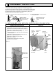
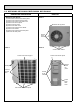
1. Removing the cabinet
(1) Remove the screw fixing the service panel. (Photo 1)
(2) Pull down the service panel and remove it. (Photo 1)
(3) Remove the screws fixing the conduit cover. (Photo 2)
(4) Remove the conduit cover. (Photo 2)
(5) Disconnect the power supply wire and indoor/outdoor
connecting wire.
(6) Remove the screws fixing the top panel. (Photo 1)
(7) Remove the top panel. (Photo 1)
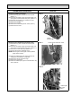
(8) Remove the screws fixing the cabinet.
(9) Remove the cabinet.
(10) Remove the screws fixing the back panel.
(11) Remove the back panel.
Photo 2
Photo 1
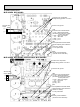
(1) Slide the sleeve and check if there is a locking lever or not.
(2) The terminal with this connector has the
locking mechanism.
Slide the sleeve.
Pull the terminal while
pushing the locking
lever.
Hold the sleeve, and
pull out the terminal
slowly.
Connector
Sleeve
Locking lever
DISASSEMBLY INSTRUCTIONS
11
<"Terminal with locking mechanism" Detaching points>
The terminal which has the locking mechanism can be detached as shown below.
There are two types (refer to (1) and (2)) of the terminal with locking mechanism.
The terminal without locking mechanism can be detached by pulling it out.
Check the shape of the terminal before detaching.
Conduit cover
Screw of the
conduit cover
Conduit plate
Screws of
the cabinet
Service
panel
Screw of the
cabinet
Screws
of the top
panel
Hooks
Screw of
the service
panel
Back
panel
Screws of
the top panel