
Service manual


60
Back side of unit
-4 14 32 50 68 86 104
0
10
20
30
40
50
60
70
80
90
100
Temperature (°F)
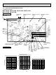
Ambient temperature thermistor (RT65)
Defrost thermistor (RT61)
Temperature (°F)
Discharge temperature thermistor (RT62)
32 50 68 86 104 122 140 158 176 194 212 230 248
0
100
200
300
400
500
600
700
32 50 68 86 104 122 140 158 176
0
20
40
60
80
100
120
140
160
180
200
Temperature (°F)
Fin temperature thermistor (RT64)
Resistance(kΩ)
Resistance(kΩ)
Resistance(kΩ)
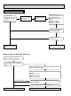
Output to drive
outdoor fan motor
(CN932)
Fin temperature
thermistor/RT64
(CN642)
Ambient temperature
thermistor /RT65
(CN643)
Discharge temperature
thermistor/RT62
(CN641)
Defrost thermistor/
RT61(CN641)
LEV
connector
(CN724)
208/230V AC
DB61
Connecting wire with
power P.C. board
(CN725)
Jumper wire for change
in defrost setting (JS)
Front side of unit
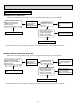
DB61
280V - 370V
DC
Smoothing capacitor
(C63C)
Smoothing capacitor
(C63A)
Smoothing capacitor
(C63B)
Rotational frequency
feedback signal of outdoor
fan motor CN931)
(+)
(+)
(+)
5V
GND
Output to
drive
compressor
(LDW,
LDV,
LDU)
LED monitor
lamp
Connector for indoor/
outdoor communication
(CN601)
(+)
(-)
1. Inverter P.C. board
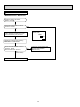
MUZ-A09NA MUZ-A12NA MUZ-A15NA MUZ-A17NA
MUY-A15NA MUY-A17NA
10-6. TEST POINT DIAGRAM AND VOLTAGE