
Service manual


53
MUZ-A24 MUY-A24 MUZ-GA24 MUY-GA24
MUZ-A09/12/15/17 MUY-A15/17
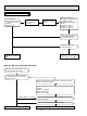
J Check of power supply
Is there voltage 208/230 VAC
between the indoor terminal
block S1 and S2?
No
Yes
Replace the indoor
electronic control P.C.
board.
Rectify indoor/outdoor
connecting wire.
Yes
If light up, OK.
If fl ash, refer to 10-3.
Does the left lamp of OPERATION
INDICATOR lamp on the indoor unit
light up?
Dose LED on the inverter P.C.
board light up or fl ash? (Refer
to 10-6.1.)
No
Replace the inverter
P.C. board.
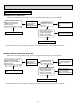
Is there voltage 280 - 370 VDC
between DB61 (+) and DB61 (–) on
the inverter P.C. board?
(Refer to 10-6.1.)
No
Check the electric parts in main circuit.
Yes
Yes
No
Disconnect the connector (CN61)
between compressor and intelligent
power module.
Turn ON power supply and press
EMERGENCY OPERATION switch.
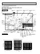
Inverter P.C. board
(Solder side)
DB61
280 - 370 VDC
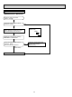
Is there voltage of 208/230 VAC in the power
supply terminal block?
Check the connecting of parts of main power
supply circuit.
Check the power supply cable.
Turn ON power supply.
Is the output voltage from the noise fi lter P.C.
board 208/230 VAC?
Replace the noise fi lter P.C. board.
No
Yes
No
Yes
Is the input voltage to the power board
208/230 VAC?
Replace the reactor.
No
Yes
Is the input voltage to the outdoor electronic
control P.C. board 294/325 VDC?
Replace the power board.
No
Replace the outdoor electronic control P.C. board.
Yes