
Service manual


46
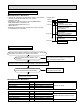
10-4. TROUBLE CRITERION OF MAIN PARTS
MUZ-A09NA MUZ-A12NA MUZ-A15NA MUZ-A17NA MUZ-A24NA
MUY-A15NA MUY-A17NA MUY-A24NA MUZ-GA24NA MUY-GA24NA
Part name Check method and criterion Figure
Defrost thermistor (RT61)
(MUZ)
Fin temperature thermistor
(RT64)
Ambient temperature ther-
mistor (RT65)
Outdoor heat exchanger
temperature thermistor
(RT68)
Measure the resistance with a tester.
Refer to 10-6. "Test point diagram and voltage", 1. "Inverter P.C. board" and
3.
"Outdoor electronic
control P.C. board”, for the chart of thermistor.
Discharge temperature
thermistor (RT62)
Measure the resistance with a tester.
Before measurement, hold the thermistor with your hands to warm it up.
Refer to 10-6. "Test point diagram and voltage", 1. "Inverter P.C. board" and
3.
"Outdoor electronic
control P.C. board", for the chart of thermistor.
Compressor (MC)
Measure the resistance between the terminals with a tester.
(Temperature 14 - 104°F)
Normal
A09/12 A15/17/24 GA24
U-V
U-W
V-W
0.43 - 0.53 Ω 0.39 - 0.49 Ω 0.86 - 1.06 Ω
Outdoor fan motor (MF)
Measure the resistance between the terminals with a tester.
(Temperature 14 - 104°F)
Color of lead wire
Normal
A09/12/15/17 A24 GA24
WHT – BLK
BLK – RED
RED – WHT
31 - 41 Ω 13 - 16 Ω
R. V. coil (21S4)
(MUZ)
Measure the resistance between the terminals with a tester.
(Temperature 14 - 104°F)
Normal
1.20 - 1.55 kΩ
Expansion valve coil (LEV)
Measure the resistance with a tester.
(Temperature: 14 - 104°F)
Color of lead wire Normal
WHT – RED
38 - 50 Ω
RED – ORN
YLW – BRN
BRN – BLU
W
U
V
WHT
RED BLK
W
U
V
WHT
RED BLK
LEV
WHT
RED
ORN
YLW
BRN
BLU