Revision E: • MUZ-GA24NA and MUY-GA24NA have been added. Please void OB451 REVISED EDITION-D. SPLIT-TYPE AIR CONDITIONERS OUTDOOR UNIT SERVICE MANUAL HFC utilized No. OB451 REVISED EDITION-E R410A Models MUZ-A09NA,- ,MUZ-A12NA,MUZ-A15NA,MUZ-A17NA,MUZ-A24NA,- ,MUY-A15NA MUY-A17NA MUY-A24NA,- ,MUZ-GA24NA,MUY-GA24NA U1 ,- U2 1 U1 ,- U2 1 U1 ,- U2 1 U1 U1 U1 Indoor unit service manual MSZ-A•NA Series (OB450) MSZ-GA•NA Series (OB450) U1 CONTENTS MUZ-A09/12/15/17NA MUY-A15/17NA 1.
Revision A: • MUZ-A09NA - U2 and MUZ-A09NA - 1 have been added. Revision B: • 10-5. ”Check of outdoor thermistors” has been corrected. Revision C: • 10-6. ”Test point diagram and voltage” has been corrected. 10-6.3. ”Outdoor electronic control P.C. board”, the chart of thermistor has been corrected. Revision D: • MUZ-A24NA - 1 , MUZ-A24NA - U2 and MUY-A24NA - 1 have been added. Revision E: • MUZ-GA24NA and MUY-GA24NA have been added.
1 TECHNICAL CHANGES MUZ09UN MUH15TN MUH24WN MU15TN MU24WN 1. 2. 3. 4. 5. → → → → → MUZ-A09NA MUZ12UN → MUZ-A12NA MUZ-A15NA MUH17TN → MUZ-A17NA MUZ-A24NA MUY-A15NA MU17TN → MUY-A17NA MUY-A24NA Outdoor unit model has been changed. Control method between indoor and outdoor unit has been changed. Refrigerant has been changed. (R22 → R410A) Fan motor has been changed. (AC → DC) Compressor has been changed. (AC → DC) MUZ-A09NA → MUZ-A09NA - 1 MUZ-A09NA - U1 → MUZ-A09NA - U2 1.
INFORMATION FOR THE AIR CONDITIONER WITH R410A REFRIGERANT • This room air conditioner adopts HFC refrigerant (R410A) which never destroys the ozone layer. • Pay particular attention to the following points, though the basic installation procedure is same as that for R22 air conditioners. As R410A has working pressure approximate 1.6 times as high as that of R22, some special tools and piping parts/materials are required. Refer to the table below.
Conversion chart of refrigerant temperature and pressure 580 R410A 435 R22 363 (PSIG) Saturated liquid pressure 508 290 218 145 73 0 -73 -22 -4 14 32 50 68 86 104 122 140 (°F) 1. Tools dedicated for the air conditioner with R410A refrigerant The following tools are required for R410A refrigerant. Some R22 tools can be substituted for R410A tools.
3. Refrigerant oil Apply the special refrigeration oil (accessories: packed with indoor unit) to the flare and the union seat surfaces. 4. Air purge • Do not discharge the refrigerant into the atmosphere. Take care not to discharge refrigerant into the atmosphere during installation, reinstallation, or repairs to the refrigerant circuit. • Use the vacuum pump for air purging for the purpose of environmental protection. 5.
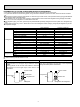
3 SPECIFICATION Item Model Cooling 1 Heating 47 Heating 17 Cooling 1 Heating 47 Heating 17 Cooling Heating Heating 1 MSZ-A09NA MSZ-A12NA 9,000 (5,500-9,000) 12,000 (5,700-12,000) 1 10,900 (5,200-12,600) 13,600 (5,200-13,600) 2 7,700 8,300 690 (390-690) 1,170 (395-1,170) 1 860 (350-1,100) 1,160 (350-1,160) 2 880 930 13.0 [17.0] 10.3 [17.0] 8.2 (7.1) 8.2 (7.1) 3.71 3.44 MUZ-A09NA - 1 MUZ-A09NA MUZ-A12NA Outdoor unit model MUZ-A09NA - U1 MUZ-A09NA - U2 Power supply V , phase , Hz 208/230, 1, 60 Max.
Item Model MSZ-A15NA MSY-A15NA MSZ-A17NA MSY-A17NA 15,000 15,000 16,200 16,200 Cooling 1 Btu/h Capacity (3,100-15,000) (3,100-15,000) (3,100-16,200) (3,100-16,200) Rated 18,000 20,100 (Minimum-Maximum) Heating 47 1 Btu/h – – (3,400-20,900) (3,400-20,900) Capacity Rated Heating 17 2 Btu/h 13,000 – 13,000 – W 1,690 (210-1,690) 1,690 (210-1,690) 2,070 (210-2,070) 2,070 (210-2,070) Power consumption Cooling 1 Rated (Minimum-Maximum) Heating 47 1 W 1,790 (250-2,330) – 2,150 (250-2,330) – Power consumption
Item Model MSZ-A24NA MSY-A24NA MSZ-GA24NA MSY-GA24NA 22,000 22,000 22,000 22,000 Cooling 1 Btu/h (4,400-22,000) (4,400-22,000) (4,400-22,000) (4,400-22,000) Capacity Rated Minimum-Maximum) 23,200 23,200 Btu/h — — Heating 47 1 (3,600-24,400) (3,600-24,400) Btu/h 15,200 — 15,200 — Capacity Rated Heating 17 2 W 2,880 (290-2,880) 2,880 (290-2,880) 2,500 (270-2,500) 2,500 (270-2,500) Power consumption Cooling 1 Rated (Minimum-Maximum) Heating 47 1 W 2,350 (260-2,570) — 2,140 (250-2,520) — Power consumption
Test condition 3, 4 Mode SEER (Cooling) ARI HSPF (Heating) Indoor air condition (˚F) Dry bulb Wet bulb Test "A" Cooling Steady State at rated compressor Speed "B-2" Cooling Steady State at rated compressor Speed "B-1" Cooling Steady State at minimum compressor Speed Low ambient Cooling Steady State at minimum compressor Speed Intermediate Cooling Steady State At Intermediate compressor Speed 5 Standard Rating-Heating at rated compressor Speed Low temperature Heating at rated compressor Speed Max temper
4 OUTLINES AND DIMENSIONS MUZ-A09NA MUZ-A12NA MUZ-A15NA MUZ-A17NA MUY-A15NA MUY-A17NA REQUIRED SPACE 4 in 4 in . or . or 2- 3/8 13/16 Oval hole 29/32 11-1/4 e mor mo re 14 1-9/16 Air out 7/8 13-9/16 11/16 Air in . 8 in 17/32 e or or m in. or m ore Open two sides of left, right, or rear side. Liquid pipe Gas pipe 5-7/8 2 11-1/32 handle 11-29/32 13/32 21-5/8 Basically open 4 inch or more without any obstruction in front and on both sides of the unit.
5 WIRING DIAGRAM MUZ-A09NA MUZ-A12NA MUZ-A15NA MUZ-A17NA 12
MUY-A15NA MUY-A17NA 13
MUZ-A24NA MUZ-A24NA- U1 14
MUZ-A24NA- 1 MUZ-A24NA- U2 15
MUY-A24NA 16
MUY-A24NA- 1 17
MUZ-GA24NA 18
MUY-GA24NA 19
6 REFRIGERANT SYSTEM DIAGRAM MUZ-A09NA MUZ-A09NAMUY-A15NA MUY-A17NA U1 MUZ-A12NA MUZ-A15NA MUZ-A17NA Unit: inch Refrigerant pipe ø3/8 (MUZ-A09/12) ø1/2 (MUZ-A15/17,MUY-A15/17) (with heat insulator) 4-way valve Muffler Stop valve (with service port) Outdoor heat exchanger Muffler Discharge temperature thermistor RT62 Service port Flared connection Service port Ambient temperature thermistor RT65 Compressor Defrost thermistor RT61 Capillary tube O.D. 0.118 × I.D. 0.071 × 23-5/8 (ø3.0 × ø1.
MUZ-A24NA MUZ-GA24NA Unit: inch Muffler 4-way valve #100 Refrigerant pipe ø5/8 (with heat insulator) Stop valve (with service port) Flared connection Discharge temperature thermistor RT62 Service port Defrost thermistor RT61 Service port Outdoor heat exchanger Ambient temperature thermistor RT65 Compressor Outdoor heat exchanger temperature thermistor RT68 Flared connection LEV Strainer Receiver #100 Stop valve Strainer #100 Capillary tube O.D. 0.142 × I.D. 0.094 × 1-31/32 (ø3.6 × ø2.
MAX. REFRIGERANT PIPING LENGTH and MAX. HEIGHT DIFFERENCE Refrigerant piping: ft. Max. Length Max. Height difference A B Model MUZ-A09NA MUZ-A12NA MUZ-A15NA MUY-A15NA MUZ-A17NA MUY-A17NA MUZ-A24NA MUY-A24NA MUZ-GA24NA MUY-GA24NA 65 Piping size O.D: in. Gas Liquid 3/8 1/4 1/2 1/4 5/8 1/4 40 100 50 Indoor unit Max. Height difference B Max. Length A Outdoor unit ADDITIONAL REFRIGERANT CHARGE (R410A: oz.) Refrigerant piping exceeding 25 ft.
7 DATA MUZ-A09NA MUZ-A12NA MUZ-A15NA MUZ-A17NA MUZ-A24NA MUZ-GA24NA MUY-A15NA MUY-A17NA MUY-A24NA MUY-GA24NA 7-1. PERFORMANCE DATA 1) COOLING CAPACITY Model MUZ-A09NA MUZ-A09NA - U1 MUZ-A09NA MUZ-A09NA - 1 U2 MUZ-A12NA MUY-A15NA MUZ-A15NA MUY-A17NA MUZ-A17NA MUY-A24NA MUZ-A24NA MUY-GA24NA MUZ-GA24NA Indoor air IWB (˚F) 71 67 63 71 67 63 71 67 63 71 67 63 71 67 63 71 67 63 71 67 63 TC 11.0 10.4 9.8 11.0 10.4 9.8 14.7 13.9 13.1 18.4 17.4 16.4 19.8 18.8 17.7 27.0 25.5 24.0 27.0 25.5 24.0 75 SHC 6.4 7.
3) HEATING CAPACITY Indoor air IDB 5 (˚F) TC TPC 75 MUZ-A09NA 70 — — MUZ-A09NA - U1 65 75 MUZ-A09NA - 1 70 — — MUZ-A09NA - U2 65 75 MUZ-A12NA 70 — — 65 75 MUZ-A15NA 70 — — 65 75 MUZ-A17NA 70 — — 65 75 MUZ-A24NA 70 — — 65 75 10.2 1.26 MUZ-GA24NA 70 11.0 1.21 65 11.6 1.16 Model 15 TC TPC 6.3 0.64 6.7 0.62 6.9 0.59 6.3 0.64 6.7 0.62 6.9 0.59 7.9 0.86 8.4 0.84 8.6 0.80 10.4 1.33 11.1 1.29 11.3 1.24 11.7 1.60 12.4 1.55 12.7 1.48 13.5 1.75 14.3 1.69 14.6 1.62 13.5 1.59 14.3 1.54 14.6 1.
7-2. PERFORMANCE CURVE Cooling MUZ-A09NA MUZ-A09NA- U1 MUZ-A09NAMUZ-A09NA- peratu re (°F ) 71 67 63 (°F) perature r WB tem take ai Indoor in 71 67 63 75 85 95 105 Outdoor intake air DB temperature (°F) 115 12 11 10 9 8 7 6 0.9 0.8 0.7 0.6 0.5 0.4 65 MUZ-A15NA MUY-A15NA B tem peratu re (°F ) 14 71 67 63 Total power consumption (kW) 10 e air W B tem peratu re (°F ) 71 67 63 F) rature (° B tempe W take air Indoor in 75 85 95 105 Outdoor intake air DB temperature (°F) 2.
MUZ-A15NA 1.9 1.8 (°F) 75 70 65 mp B te ir D ke a ta in r doo Total power consumption (kW) Total power consumption (kW) 10 re eratu 1.7 1.6 In 1.5 1.4 1.3 15 25 35 45 55 Outdoor intake air WB temperature (°F) 16 Airflow = 568 CFM Total capacity ( 103 Btu/h) 30 28 e tur oor Ind ke inta D air °F re ( atu per em Bt 20 Airflow = 568 CFM 28 26 24 B D air ke inta or o Ind 22 20 18 12 2.4 2.2 2.0 ke r inta Indoo ) re (°F peratu B tem air D 75 70 65 1.8 1.6 1.
MUZ-A09NAMUZ-A09NA- 1 U2 (PSIG) 480 460 86 80 75 70 Condensing pressure 440 420 ) 400 re atu 340 em Bt 360 r pe D or o Ind 320 300 280 68 70 75 80 85 rature (°F) Indoor DB tempe 86 Suction pressure 380 (°F (PSIG) 170 165 160 155 150 145 140 135 130 125 120 115 110 68 70 90 95 100 105(°F) Outdoor ambient temperature 80 75 70 75 80 85 90 95 100 105(°F) Outdoor ambient temperature MUZ-A12NA (PSIG) 500 86 80 75 70 Condensing pressure 460 °F) re ( atu r e mp 420 oor I
MUZ-A17NA MUY-A17NA (PSIG) 580 Condensing pressure 540 86 80 75 70 500 ) (°F ture 460 or ndo DB tem Suction pressure 420 a per I 380 340 300 260 68 70 75 80 85 (PSIG) 140 135 130 125 120 115 110 105 100 95 90 85 80 68 70 90 95 100 105(°F) Outdoor ambient temperature rature (°F) 86 Indoor DB tempe 80 75 70 75 80 85 90 95 Outdoor ambient temperature 100 105(°F) MUZ-A24NA MUY-A24NA (PSIG) 580 86 80 75 70 500 °F) re ( 460 tu era 420 oor Ind 380 DB p tem 340 300 260 68 70
Heating Data is based on the condition of outdoor humidity 75%. Air flow should be set to High speed. Data is for heating operation without any frost.
MUZ-A15NA (PSIG) 620 (PSIG) 160 580 500 460 420 oor Ind 380 DB ) (°F ture era p tem 140 130 Suction pressure Condensing pressure 75 70 65 150 75 70 65 540 340 300 58Hz 260 e( tur ra e p tem 120 110 B rD oo Ind 100 90 °F ) 58Hz 80 220 70 180 60 140 50 100 14 20 25 30 35 40 45 50 55 60 65 70(°F) 14 20 25 30 35 40 45 50 60 55 65 70(°F) Outdoor ambient temperature Outdoor ambient temperature MUZ-A17NA (PSIG) 620 (PSIG) 160 580 460 420 130 em Bt D oor 14
MUZ-GA24NA 380 75 Condensing pressure 360 340 ( °F ture era mp e t B rD doo 320 300 ) In 280 70 65 58Hz 260 240 220 200 5 10 15 20 25 30 35 40 45 50 55 60 65 70(°F) (PSIG) 170 160 150 140 130 120 110 100 90 80 70 60 50 40 75 70 65 ( ure rat Suction pressure (PSIG) °F) e mp e Bt rD oo d n I 5 58Hz 10 15 20 25 30 35 40 45 50 55 60 65 70(°F) Outdoor ambient temperature Outdoor ambient temperature 31
7-4. STANDARD OPERATION DATA Model MUZ-A09NA Item Total Capacity Cooling Heating Cooling Heating Cooling Heating Btu/h 9,000 10,900 9,000 10,900 12,000 13,600 SHF — 0.71 — 0.71 — 0.70 — Input kW 0.690 0.860 0.690 0.860 1,170 1,160 Rated frequency Hz 50 61 50 63 76 76 Indoor unit Refrigerant circuit Electrical circuit Power supply (V, Phase, Hz) Input Indoor unit MSZ-A09NA MSZ-A12NA 208 / 230, 1, 60 208 / 230, 1, 60 0.016 0.
MSZ-A15NA Unit MSZ-A15NA MSY-A15NA Cooling Btu/h 15,000 SHF - 0.65 — 0.65 — Input kW 1.69 1.79 2.07 2.15 Rated frequency Hz 77 78 89 88 Model Item Total Capacity Indoor unit Electrical circuit Refrigerant circuit Fan motor current MSZ-A17NA, MSY-A17NA 208 / 230, 1, 60 208 / 230, 1, 60 0.030 0.030 0.31 / 0.28 MUZ-A15NA MUZ-A15NA MUY-A15NA 208 / 230, 1, 60 0.31 / 0.28 MUZ-A17NA MUZ-A17NA MUY-A17NA 208 / 230, 1, 60 kW 1.660 Comp. current A 7.56 / 6.
MSZ-A24NA Unit MSZ-A24NA MSY-A24NA Cooling Btu/h 22,000 SHF - 0.63 — 0.63 — Input kW 2.88 2.35 2.50 2.14 Rated frequency Hz 110 101 101 96 Model Item Total Capacity Indoor unit MSZ-GA24NA Heating MSZ-GA24NA MSY-GA24NA Cooling 23,200 22,000 23,200 MSZ-A24NA, MSY-A24NA Refrigerant circuit Electrical circuit Power supply (V, Phase, Hz) kW Fan motor current 0.053 A MUZ-A24NA MUY-A24NA Outdoor unit Power supply (V, phase, Hz) Input kW 2.827 Comp. current A 12.81 / 11.
7-5. CAPACITY AND INPUT CORRECTION BY INVERTER OUTPUT FREQUENCY Correction of Cooling total input Correction of Cooling capacity 1.5 Capacity correction factors 2.0 Input correction factors Capacity correction factors 1.5 1.0 1.0 0.5 0.5 Correction of Heating total input 2.0 Correction of Heating capacity Input correction factors MUZ-A09NA MUZ-A09NA - U1 1.5 1.0 0.5 1.5 1.0 0.5 0.0 0.0 0.0 0.
MUZ-A17NA MUY-A17NA 0.5 1.5 1.0 0.5 Correction of Heating capacity 1.5 Input correction factors 1.0 Correction of Cooling total input Capacity correction factors 1.5 Input correction factors Capacity correction factors 1.5 MUZ-A17NA Correction of Cooling capacity 1.0 0.5 Correction of Heating total input 1.0 0.5 0.0 0.0 0.0 0.
8 ACTUATOR CONTROL MUZ-A09NA MUZ-A12NA MUZ-A15NA MUZ-A17NA MUZ-A24NA MUY-A15NA MUY-A17NA MUY-A24NA MUZ-GA24NA MUY-GA24NA 8-1. OUTDOOR FAN MOTOR CONTROL The fan motor turns ON/OFF, interlocking with the compressor. [ON] The fan motor turns ON 5 seconds before the compressor starts up. [OFF] The fan motor turns OFF 15 seconds after the compressor has stopped running. 5 seconds 15 seconds ON Compressor OFF ON Outdoor fan motor OFF 8-2. R.V. COIL CONTROL(MUZ) Heating . . . . . . . . . . . . . . . . .
9 SERVICE FUNCTIONS MUZ-A09NA MUZ-A12NA MUZ-A15NA MUZ-A17NA CHANGE IN DEFROST SETTING When the JS wire of the outdoor Inverter P.C. board is cut/soldered, the defrost finish temperature is changed. (Refer to 10-6.1.) Defrost finish temperature °F (°C) Jumper wire MUZ-A09/12NA MUZ-A15/17NA Soldered (Initial setting) 50 (10) 41 (5) JS None (Cut) 55 (13) 46 (8) 10 TROUBLESHOOTING MUZ-A09NA MUZ-A12NA MUZ-A15NA MUZ-A17NA MUZ-A24NA MUY-A15NA MUY-A17NA MUY-A24NA MUZ-GA24NA MUY-GA24NA 10-1.
10-2. FAILURE MODE RECALL FUNCTION Outline of the function This air conditioner can memorize the abnormal condition which has occurred once. Even though LED indication listed on the troubleshooting check table (10-3.) disappears, the memorized failure details can be recalled. 1. Flow chart of failure mode recall function for the indoor/outdoor unit This figures show about MSZ-A09/12/15/17. Operational procedure The cause of abnormality cannot be found because the abnormality does not recur.
2. Flow chart of the detailed outdoor unit failure mode recall function Operational procedure The outdoor unit might be abnormal. Confirm if outdoor unit is abnormal according to the following procedures. Confirm that the remote controller is in the failure mode recall function. With the remote controller headed towards the indoor unit, press TOO COOL or TOO WARM button to adjust the set temperature to 77˚F (25˚C).
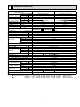
3. Outdoor unit failure mode table MUZ-A09/12/15/17NA MUY-A15/17NA The left lamp of OPERATION INDICATOR lamp (Indoor unit) OFF Abnormal point (Failure mode / protection) None (Normal) LED indication (Outdoor P.C. board) — Outdoor power system 2-time flash 2.5 seconds OFF — 3-time flash Discharge temperature 2.5 seconds OFF thermistor Defrost thermistor (MSZ) Fin temperature thermistor 4-time flash 2.5 seconds OFF P.C.
MUZ-A24NA MUY-A24NA MUZ-GA24NA MUY-GA24NA The left lamp of OPERATION INDICATOR lamp (Indoor unit) Abnormal point (Failure mode / protection) OFF None (Normal) 2-time flash Outdoor power system 3-time flash 4-time flash 5-time flash 6-time flash 7-time flash LED indication (Outdoor P.C. board) LED1 Correspondence Indoor/outdoor unit failure mode recall function — — • Check the connection of the compressor connecting wire. • Refer to 10-5. "How to check inverter/compressor".
10-3. TROUBLESHOOTING CHECK TABLE MUZ-A09/12/15/17NA MUY-A15/17NA No. 1 Symptom LED indication 2 3 6-time flash 2.5 seconds OFF 14-time flash 2.5 seconds OFF 4 5 7 'Outdoor unit 2-time flash stops and 2.5 seconds OFF restarts 3 minutes later' is repeated. 3-time flash 2.5 seconds OFF 8 4-timeflash 2.5 seconds OFF 9 5-time flash 2.5 seconds OFF 10 8-time flash 2.5 seconds OFF 11 10-time flash 2.5 seconds OFF 6 12 13 unit 14 Outdoor operates. 15 16 Outdoor unit 17 operates. 12-timeflash 2.
MUZ-A24NA MUY-A24NA MUZ-GA24NA MUY-GA24NA No. 1 Symptom LED indication LED1(Red) LED2(Yellow) Outdoor unit does not operLightning ate.
No. Symptom 20 Outdoor unit operates. 21 LED indication Abnormal point/ Condition LED1(Red) LED2(Yellow) Primary current protection Once Lighting Secondary current protection High-Pressure protection (MUZ) Twice Lighting Defrosting in cooling 9 times Lighting Lighting Normal 3 times 23 4 times 24 5 times 25 Outdoor unit operates Correspondence These symptoms do not mean any abnormality of the product, but check the following points. The current of the compressor exceeds 15 A.
10-4. TROUBLE CRITERION OF MAIN PARTS MUZ-A09NA MUZ-A12NA MUZ-A15NA MUZ-A17NA MUZ-A24NA MUY-A15NA MUY-A17NA MUY-A24NA MUZ-GA24NA MUY-GA24NA Part name Check method and criterion Defrost thermistor (RT61) (MUZ) Fin temperature thermistor Measure the resistance with a tester. (RT64) Ambient temperature therRefer to 10-6. "Test point diagram and voltage", 1. "Inverter P.C. board" and 3. mistor (RT65) "Outdoor electronic control P.C. board”, for the chart of thermistor.
10-5. Troubleshooting flow A How to check inverter/compressor MUZ-A09/12/15/17 MUY-A15/17 Disconnect the connector (CN61) between compressor and the intelligent power module (IPM). Check the voltage between terminals. Is the voltage balanced? See 10-5. “Check of open phase” . Check the resistance of the intelligent power module. No See 10-5. “Check of intelligent power module”. Yes Check the compressor. See 10-5. Is the resistance infinite? “Check of compressor” . Yes Replace the inverter P.
B Check of open phase MUZ-A09/12/15/17 MUY-A15/17 ● With the connector between the compressor and the intelligent power module disconnected, activate the inverter and check if the inverter is normal by measuring the balance of voltage between the terminals. Inverter P.C. board (Parts side) Output voltage is 50 - 130 V. (The voltage may differ according to the tester.) << Operation method>> Start cooling or heating operation by pressing EMERGENCY OPERATION switch on the indoor unit.
F Check of compressor operation time MUZ-A09/12/15/17 MUY-A15/17 ● Connect the compressor and activate the inverter. Then measure the time until the inverter stops due to over current. <> Start heating or cooling operation by pressing EMERGENCY OPERATION switch on the indoor unit. (TEST RUN OPERATION: Refer to 7-7.) <> Measure the time from the start of outdoor fan running to the stop of compressor due to overcurrent.
H Check of R.V. coil MUZ-A09/12/15/17 First of all, measure the resistance of R.V. coil to check if the coil is defective. Refer to 10-4. In case CN721 is disconnected or R.V. coil is open, voltage is generated between the terminal pins of the connector although no signal is being transmitted to R.V. coil. Check if CN721 is connected. Unit operates COOL mode even if it is set to HEAT mode. Disconnect connector (CN61) between the compressor and the intelligent power module.
MUZ-A24 MUZ-GA24 • Heating operation does not work. 1. Disconnect the lead wire leading to the compressor. 2. 3 minutes after turning on the power supply, start EMERGENCY OPERATION in HEAT mode. Is there voltage of 208/230 VAC between pin1 and pin 2 at connector CN912? Yes No Turn OFF power supply of indoor and outdoor unit. Disconnect the connector CN912 in noise filter P.C. board. Is there normal resistance to R.V. coil? No Replace the R.V. coil. 1.
I Check of outdoor fan motor MUZ-A09/12/15/17 MUY-A15/17 Is the resistance between each terminal of outdoor fan motor Yes normal? (Refer to 10-4.) No Disconnect CN932 from the inverter P.C. board. Rotate the outdoor fan slowly by hand, and measure the voltage of CN931 (Measurement of feedback output). Between 1(+) and 5(-) Between 2(+) and 5(-) Between 3(+) and 5(-) Turn ON the power supply.
J Check of power supply MUZ-A09/12/15/17 MUY-A15/17 Disconnect the connector (CN61) between compressor and intelligent power module. Turn ON power supply and press EMERGENCY OPERATION switch. Does the left lamp of OPERATION INDICATOR lamp on the indoor unit light up? Yes Is there voltage 280 - 370 VDC between DB61 (+) and DB61 (–) on the inverter P.C. board? (Refer to 10-6.1.) No Rectify indoor/outdoor connecting wire.
K Check of current-limiting resistor MUZ-A09/12/15/17 MUY-A15/17 When the current-limiting resistor is open, the rush current limiting relay (X64) may not work properly. Is the resistance of currentlimiting resistor (R64A or R64B) on the power P.C. board normal? (Normal resistance: 5 Ω ±5%) No Yes Turn ON the power supply and press EMERGENCY OPERATION switch. Does LED on the inverter P.C.
L Check of LEV (Expansion valve) MUZ-A09/12/15/17 MUY-A15/17 This figures show about MSZ-A09/12/15/17. Turn ON the power supply. While pressing both OPERATION SELECT button and TOO COOL button on the remote controller at the same time, press RESET button. First, release RESET button. And release the other two buttons after all LCD in operation display section of the remote controller is displayed after 3 seconds.
M Check of inverter P.C. board MUZ-A09/12/15/17 MUY-A15/17 Check the outdoor fan motor. (Refer to 10-5. .) Is the fuse (F901) blown on the inverter P.C. board? No Yes Inverter P.C. board (Solder side) Check the connection of the connectors. (CN931, CN932) of outdoor fan motor. If the connection is poor, correct it. CN931 CN932 Operate the outdoor unit by starting EMERGENCY OPERATION. Check the LED indication on the inverter P.C. board.
N How to check miswiring and serial signal error Turn OFF the power supply. Is there rated voltage in the power supply? Check the power supply. No Yes Turn ON the power supply. Is there rated voltage between outdoor terminal block S1 and S2? Yes • Check the wiring. • Check the fuse (F65). (For MUZ-A24NA- 1 , MUZ-A24NA- U2 , MUY-A24NA- 1 , MUZGA24, MUY-GA24.) No Press EMERGENCY OPERATION switch once.
O Electromagnetic noise enters into TV sets or radios Is the unit grounded? No Ground the unit. Yes Is the distance between the antennas and the indoor unit within 9.91 ft., or is the distance between the antennas and the outdoor unit within 9.91 ft.? Yes Extend the distance between the antennas and the indoor unit, and/or the antennas and the outdoor unit. Yes Extend the distance between the TV sets and/or radios and the indoor unit, or the TV sets or radios and the outdoor unit.
P Check of bus-bar voltage MUZ-A24NA MUY-A24NA MUZ-GA24NA MUY-GA24NA •Check the voltage of power supply. •Confirm outdoor unit failure mode recall function. (Refer to 10-2.2) Confirm LED1 indication lamp on the outdoor electronic control P.C. board. Blink 5 times Replace the power board. Blink 6 times Replace the outdoor electronic control P.C. board. Turn ON power supply. Start operation. Confirm LED1 indication lamp on the outdoor electronic control P.C. board.
10-6. TEST POINT DIAGRAM AND VOLTAGE 1. Inverter P.C. board MUZ-A09NA MUZ-A12NA MUZ-A15NA MUZ-A17NA MUY-A15NA MUY-A17NA Back side of unit DB61 280V - 370V DC (-) (+) Smoothing capacitor (C63C) 208/230V AC DB61 Smoothing capacitor (C63B) Smoothing capacitor (C63A) Rotational frequency feedback signal of outdoor fan motor CN931) LED monitor lamp Output to drive compressor (LDW, LDV, LDU) Jumper wire for change Connecting wire with in defrost setting (JS) power P.C.
2. Power P.C. board MUZ-A09NA MUZ-A12NA MUZ-A15NA MUZ-A17NA MUY-A15NA MUY-A17NA Back side of unit Varistor (NR63) Varistor (NR62) Varistor (NR64) Front side of unit 208/230 VAC MUZ R.V.coil (CN721) 208/230 VAC Connecting wire with inverter P.C.
3. Outdoor electronic control P.C. board MUZ-A24NA MUY-A24NA MUZ-GA24NA MUY-GA24NA Defrost thermistor (RT61) Ambient temperature thermistor (RT65) Fin temperature thermistor (RT64) Outdoor heat exchanger temperature thermistor (RT68) 200 400 300 200 Resistance (kΩ) 500 90 160 140 120 100 80 60 20 10 0 CN781 -4 14 32 50 68 86 Temperature (°F) 104 ( (–) ( (+) ( (+) (–) (+) (+) (–) GND (power board) Rush current relay (–) 12V R.V.
4. Noise filter P.C. board MUZ-A24NA MUY-A24NA MUZ-GA24NA MUY-GA24NA CN901 To electronic CN902 CN903 control To power To power P.C. board board board { { 208/230 VAC 60Hz Input { { MUZ CN912 R.V.
5. Outdoor power board MUZ-A24NA MUY-A24NA Connect to the compressor Voltage among phases: 5 to 180 V 294-370 VDC Output (Red) (+) 1 Connect to the ground CN2 Connect to the controller board (+)1-5(–): Signal transmission (To electronic control P.C. board) 5 V DC pulse wave (+)2-5(–): Zero cross signal 3-4 : Not used (+)6-5(–): 15 V (+)7-5(–): 15 V (–) 3 (White) CN3 Fin temperature thermistor RT64 reception (From electronic ) Signal control P.C.
11 DISASSEMBLY INSTRUCTIONS <"Terminal with locking mechanism" Detaching points> The terminal which has the locking mechanism can be detached as shown below. There are two types (refer to (1) and (2)) of the terminal with locking mechanism. The terminal without locking mechanism can be detached by pulling it out. Check the shape of the terminal before detaching. (1) Slide the sleeve and check if there is a locking lever or not.
OPERATING PROCEDURE PHOTOS 2. Removing the inverter assembly, inverter P.C. board and power P.C. board Photo 3 (1) Remove the top panel, cabinet and service panel. (Refer to 1.) (2) Disconnect the power supply and indoor/outdoor connecting wire and remove the back panel. (Refer to 1.) (3) Disconnect the ground wires (Photo 3), the lead wire to the reactor and the following connectors: CN721 (4-way valve coil)
OPERATING PROCEDURE PHOTOS 5. Removing outdoor fan motor Photo 6 (1) Remove the top panel, cabinet and service panel. (Refer to 1.) (2) Disconnect the power supply and indoor/outdoor connecting wire and remove the back panel. (Refer to 1.) (3) Disconnect the connectors for outdoor fan motor. (4) Remove the propeller nut. (5) Remove the propeller. (6) Remove the screws fixing the fan motor. (Photo 7) (7) Remove the fan motor. Defrost thermistor Photo 7 6.
11-2. MUZ-A24NA MUY-A24NA MUZ-GA24NA MUY-GA24NA OPERATING PROCEDURE PHOTOS 1. Removing the cabinet Photo 1 (1) Remove the screws of the service panel. (2) Remove the screws of the top panel. (3) Remove the screw of the valve cover. (4) Remove the service panel. (5) Remove the top panel. (6) Remove the valve cover. (7) Remove the screws of the cabinet. (8) Remove the cabinet. (9) Remove the screws of the back panel. (10) Remove the back panel.
OPERATING PROCEDURE PHOTOS 2. Removing the inverter assembly, inverter P.C. board and power board Photo 4 Screws of the power board assembly (1) Remove the top panel, cabinet and service panel. (Refer to 1.) (2) Remove the back panel. (Refer to 1.) (3) Disconnect the following connectors: CN931 and CN932 (Fan motor) CN795 (LEV) CN661 (Discharge temperature thermistor, defrost thermistor (MUZ) and outdoor heat exchanger temperature thermistor)
OPERATING PROCEDURE PHOTOS 4. Removing the defrost thermistor (MUZ), discharge temperature thermistor, outdoor heat exchanger temperature thermistor and ambient temperature thermistor Photo 5 Discharge temperature thermistor (1) Remove the top panel, cabinet and service panel. (Refer to 1.) (2) Remove the back panel. (Refer to 1.) (3) Remove the inverter assembly. (Refer to 2.) (4) Pull out the defrost thermistor from its holder.
OPERATING PROCEDURE PHOTOS 6. Removing the compressor and 4-way valve Photo 8 (1) Remove the top panel, cabinet and service panel. (Refer to 1.) (2) Remove the back panel. (Refer to 1.) (3) Remove the inverter assembly. (Refer to 2.) (4) Recover gas from the refrigerant circuit. NOTE: Recover gas from the pipes until the pressure gauge shows 0 PSIG. (5) Detach the welded part of the suction and the discharge pipe connected with compressor. (Photo 9) (6) Remove the compressor nuts.
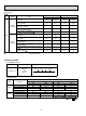
12 PARTS LIST 12-1. PARTS LIST (non-RoHS compliant) MUZ-A09NA MUZ-A12NA MUZ-A15NA MUZ-A17NA MUY-A15NA MUY-A17NA 1.
1. OUTDOOR UNIT STRUCTURAL PARTS AND FUNCTIONAL PARTS Part numbers that are circled are not shown in the illustration. No. 1 2 3 4 5 6 7 8 9 10 11 12 13 14 15 16 17 18 19 20 21 Part No.
MUZ-A09NA MUZ-A12NA MUZ-A15NA MUZ-A17NA MUY-A15NA MUY-A17NA 2.
2. OUTDOOR UNIT ELECTRICAL PARTS No. 1 2 3 4 5 6 7 Part No. E02 838 337 E02 A54 444 E02 A54 490 E02 927 306 E02 927 308 E02 A54 374 E02 A55 374 E02 A54 451 E02 A55 451 8 E02 A56 451 E02 A57 451 Part name Symbol in Wiring Diagram REACTOR L61 POWER P.C. BOARD R.V. COIL 21S4 RT61,RT62 THERMISTOR SET AMBIENT TEMPERATURE THERMISTOR RT65 TERMINAL BLOCK TB1 TERMINAL BLOCK TB2 INVERTER P.C.
MUZ-A24NA MUY-A24NA 3.
3. OUTDOOR UNIT STRUCTURAL PARTS, ELECTRICAL PARTS AND FUNCTIONAL PARTS Part numbers that are circled are not shown in the illustration. No. Part No.
12-2. RoHS PARTS LIST (RoHS compliant) MUZ-A09NA MUZ-A12NA MUZ-A15NA MUZ-A17NA MUY-A15NA MUY-A17NA 1.
1. OUTDOOR UNIT STRUCTURAL PARTS AND FUNCTIONAL PARTS No. 1 2 3 4 5 6 7 8 9 10 11 12 13 14 15 16 17 18 19 20 21 RoHS Part numbers that are circled are not shown in the illustration. Part No.
MUZ-A09NA MUZ-A12NA MUZ-A15NA MUZ-A17NA MUY-A15NA MUY-A17NA 2.
No. RoHS 2. OUTDOOR UNIT ELECTRICAL PARTS Part No. 1 2 3 4 G G G G E12 838 337 E12 A54 444 E12 A54 490 E12 927 306 5 G 6 7 G G G G G G G G G G G G 8 Part name REACTOR POWER P.C. BOARD R.V. COIL THERMISTOR SET TEMPERATURE E12 927 308 AMBIENT THERMISTOR E12 A54 374 TERMINAL BLOCK E12 A55 374 TERMINAL BLOCK E12 A54 451 E12 B49 451 E12 A55 451 E12 A56 451 E12 A57 451 INVERTER P.C.
MUZ-A24NA MUY-A24NA MUZ-GA24NA MUY-GA24NA 3.
3. OUTDOOR UNIT STRUCTURAL PARTS, ELECTRICAL PARTS AND FUNCTIONAL PARTS No. 1 2 3 4 5 6 7 8 9 10 11 12 13 14 15 16 17 18 19 20 21 22 23 24 25 26 27 28 29 30 31 RoHS Part numbers that are circled are not shown in the illustration. Part No.
13 OPTIONAL PARTS 13-1. DRAIN SOCKET Model Part No. MUZ-A09/12/15/17NA MUY-A15/17NA MAC-851DS 13-2. DRAIN SOCKET ASSEMBLY Model MUZ-A24NA MUY-A24NA MUZ-GA24NA MUY-GA24NA Part No. MAC-811DS HEAD OFFICE: TOKYO BLDG., 2-7-3, MARUNOUCHI, CHIYODA-KU, TOKYO 100-8310, JAPAN © Copyright 2006 MITSUBISHI ELECTRIC CO.,LTD Distributed in Mar. 2009. No. OB451 REVISED EDITION-E 4 Distributed in May. 2008. No. OB451 REVISED EDITION-D 6 Distributed in Nov. 2007. No. OB451 REVISED EDITION-C 7 Distributed in Feb.