
Instruction manual


App - 10
APPENDICES
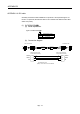
(2) Voltage-output/Open-collector type
(a) Connection diagram
Make the cable within 10m(32.81ft.).
Attach a ferrite core included with the internal I/F connector set within 1 to
5(0.39 to 1.97)[cm(inch)] from the Motion CPU module.
Cable cross-section diagram
: Twisted pair (5V/SG)
: Core
: Twisted pair for signal
(HB/SG, HA/SG, DI1/COM, DI2/COM, DI3/COM, DI4/COM)
HDR-E50MSG1+ (Connector)
HDR-E50LPH (Connector case)
CPU module side
A
Ferrite core (TDK make)
Type: ZCAT2032-0930
Solderless terminal
View A
26
5025
1
5V
41
HBH
HBL
HAH
HAL
HB
HA
SG
SG
5V
DI1
COM
DI3
DI2
COM
DI4
FG
SG
22
24
18
20
23
19
13
38
40
39
6
1
4
5
2
3
Shell
DI1
DI3
DI2
DI4
DICOM
Input signal/mark detection input side
FG
Voltage-output/Open-collector type
Manual pulse generator/
incremental synchronous encoder sid
e
5V
5VGND
HA
HB
: Twisted pair cable
(Note): Wire the cable as shown in figure below so that twisted pair for signal do not touch.