
Instruction manual


7 - 8
7 EMC DIRECTIVES
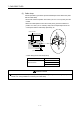
7.1.4 Example of measure against noise
SSCNET cable
Control panel
AC power
supply
MCCB
1)
Noise ferrite
(FR-BLF)
2)
3)
4)
Encoder cable
Encoder
(Q171ENC-W8/
Q170ENC)
Manual pulse
generator
(MR-HDP01)
Limit switch
Battery holder
unit
(Q170DBATC)
(Note-1)
Manual pulse generator/
DI cable
: AD75CK cable clamp
: Ferrite core (ZCAT3035-1330)
QI60 Q172D
LX
Q61P Q173D
PX
Q172D
EX
QX /
QY
Q6 AD
/DA
QnUD
CPU
Ethernet cable
(Shield twisted pair of category 5 or more)
: Ferrite core (ZCAT2032-0930)
(It is packed together with internal I/F
connector set)
Q17 D(S)
CPU
5)
(Note-1): Q173DCPU(-S1)/Q172DCPU(-S1) only
1) Ground the FG terminal of the Motion controller and 24VDC power supply module to the control panel.
2) Measure against noise of the power supply cable
• Wire the power supply cable as short as possible using the twisted cable.
• Set a line filter (FR-BLF) near the exit/entrance of control panel and in secondary side of MCCB. (Approx. 4 turn)
3) Measure against noise of the encoder cable
• When the cables are extracted from the control panel, ground the cables at a position 5 to 10cm (1.97 to 3.94inch) away from the exit/entrance
of the control panel with the cable clamp, etc.
• Refer to the Section 2.5.5 and Appendix 1.2 for encoder cable.
Use shielded twisted pair cable.
4) Measure against noise of the manual pulse generator/external signal input cable
• When the cables are extracted from the control panel, ground the cables at a position 5 to 10cm (1.97 to 3.94inch) away from the exit/entrance
of the control panel with the cable clamp, etc.
• Refer to the Section 2.5.6 for manual pulse generator.
Use shielded twisted pair cable.
• Refer to the Section 2.5.4 for external signal input.
Use shielded twisted pair cable between the external signal and COM signal.
• When the cables are connected to internal I/F connector of Q173DSCPU/Q172DSCPU and extracted from the control panel, ground the
cables at a position 20 to 30cm (1.97 to 3.94inch) away from the module with the cable clamp, etc. Use a shielded cable.
• Refer to the Section 2.5.1and Appendix 1.5 for internal I/F connector cable.
5) Measure against noise of the internal I/F cable
• When the cables are extracted from the control panel, ground the cables at a position 20 to 30cm (1.97 to 3.94inch) away from the module
with the cable clamp, etc. Use a shielded cable.
(1) Refer to Section 2 for the following cables.
• Ethernet cable
• USB cable
• SSCNET
cable
• Battery cable
• Forced stop input cable