
Instruction manual


2 - 81
2 SYSTEM CONFIGURATION
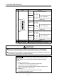
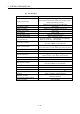
(b) Input/output
Item Specifications
Number of input points
32 points
2 lines
(PLC CPU control 32 points + Motion CPU control 32 points,
Safety input 20 points
2 lines,
Feedback input for output 12 points 2 lines
)
Input isolation method Photocoupler
Rated input voltage 24VDC (+10/-10%), Negative common type
Maximum input current Approx. 4mA
Input resistance Approx. 8.2k
Input ON voltage/current 20VDC or more/3.0mA or more
Input OFF voltage/current 5VDC or less/1.7mA or less
Input response time
PLC CPU control I/O : 10ms (initial value of digital filter)
Motion CPU control I/O : 15ms (CR filter)
Input common method
32 points/common
(PLC I/O and Motion I/O are separated.)
Number of output points
12 points
2 lines
(PLC CPU control 12 points + Motion CPU control 12 points)
Output isolation method Photocoupler
Rated output voltage 24VDC (10%), Source type
Maximum load current
(0.1A
8 points, 0.2A 4 points) 2 lines
Common current: 1.6A or less for each connector
Maximum inrush current 0.7A 10ms or less (0.2A output pin: 1.4A 10ms or less)
Response time 1ms or less
Output common method
12 points/common
(PLC I/O and Motion I/O are separated.)
Operation indicator (input/output) ON indication (LED) (indicates PLC CPU's 32 points)
Communication with PLC CPU Parallel bus communication (Via main base unit)
Communication with Motion CPU Serial communication (RS-485), Q173DSXYCBL M cable use
Applicable connector for the external
connection
A6CON1 (Attachment),
A6CON2, A6CON3, A6CON4 (Optional)
Applicable connector/
Terminal block converter module
A6TBXY36 (Optional)
Number of modules Up to 3 modules