
Instruction manual


2 - 79
2 SYSTEM CONFIGURATION
2.5.7 Q173DSXY Safety signal module
Q173DSXY is used to input/output the safety signal.
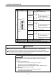
(1) Q173DSXY name of parts
Q173DSXY
PLC
IO
Motion
IO
Q173DSXY
FRONTRIO2 RIO1 SW
7
8
0
F
6
E
5
D
4
C
3
B
2
A
1
9
2)
1)
3)
11)
4)
7)
6)
5)
9) 8) 10)
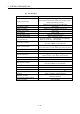
No. Name Application
1) Module fixing hook
Hook used to fix the module to the base unit.
(Single-motion installation)
2) Input indicator LED
Display the input status from the external equipment.
LED Details
0 to 1F
Display for I/O signal status of PLC CPU
side.
3) PLC IO connector Input connector of the PLC CPU.
4) Motion IO connector Input connector of the Motion CPU.
5) Module mounting lever Used to install the module to the base unit.
6) Module fixing screw hole
Hole for the screw used to fix to the base unit
(M312 screw: Purchase from the other supplier)
7) Module fixing projection Projection used to fix to the base unit.
8) RIO1 connector
RIO communication to Motion CPU
(For connection to Motion CPU or Q173DSXY installed on the
left)