
Instruction manual


2 - 76
2 SYSTEM CONFIGURATION
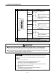
(b) Interface between PULSER connector and manual pulse
generator (Differential-output type)/Incremental synchronous
encoder
5V
SG
A
A
B
B
Power supply
5VDC
(Note-2)
A17 A12 A7
A16 A11 A6
B16 B11 B6
B17 B12 B7
123
Signal name
Input or
Output
Wiring example Internal circuit Specification Description
PIN No.
Power
supply
P5
(Note)
B18 B13 B8
A19
B19
A14
B14
A9
B9
SG
For connection manual
pulse generator
Phases A, B
Phase difference
Pulse width
(1) Positioning address
increases if Phase A
leads Phase B.
(2) Positioning address
decreases if Phase B
leads Phase A.
20 s or more
5 s
or more
Phase A
Phase B
2.5 s or more
Leading edge, Trailing
edge time 1 s or less
5 s
or more
(Duty ratio: 50% 25%)
Rated input voltage
5.5VDC or less
HIGH level
2.0 to 5.25VDC/
2mA or less
LOW level
0.8VDC or less
26LS31 or
equivalent
Manual
pulse
generator,
phase A
Manual
pulse
generator,
phase B
A18 A13 A8
Select type
signal
HPSEL
HPSEL
A
HA P
A
HA P
Input
A
HA P
A
HA P
(Note-1): The 5V(P5)DC power supply from the Q173DPX must not be used if a separate power supply is
applied to the Manual pulse generator/Incremental synchronous encoder.
If a separate power supply is used, be sure it is 5V voltage. Anything else may cause a failure.
(Note-2): Connect HPSEL to the SG terminal if the manual pulse generator (differential-output type)
/incremental synchronous encoder is used.
Manual
pulse
generator/
Incremental
synchronous
encoder