
User`s manual


6 - 27
6 INSPECTION AND MAINTENANCE
Input Circuit Troubleshooting and Corrective Action (Continued)
Condition Cause Corrective action
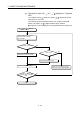
Example 5
Input signal
is not
turned
OFF.
• Sneak path due to the use of two power
supplies.
Input module
E
1
E
2
>
E
2E
1
• Use only one power supply.
• Connect a sneak path prevention diode.
(Figure below)
Input module
E
1
E
2
Example 6
False input
due to
noise
Depending on response time setting, noise is
imported as input.
Change the response time setting.
Example : 1 [ms] 5[ms]
(When excessive noise is cyclic, shorter
response time setting may produce a higher
effect.) When the above action does not have
an effect, take measures against noise to block
excessive noise, e.g. avoid tying the power
cables and control cables in a bundle, and add
surge absorbers to the noise sources such as
the relays and contactors used with the same
power supply.
<Calculation example of Example 4>
If a switch with LED display is connected to Q172DLX, and current of 4 [mA] is
leaked.
Motion CPU
module
Leakage
current 4[mA]
24[VDC]
3.6[k ]
Q172DLX
(a) Because the condition for OFF voltage (18[mA]) of Q172DLX
is not
satisfied. Connect a resistor as shown below.
Input impedance
24[VDC]
4[mA]
I
R=
3.82[mA]
Q172DLX
Iz=0.18[mA]
5.6[k ]
3.6[k ]
(b) Calculate the connecting resistor value R as indicated below.
To satisfy the 0.18 [mA] OFF current of the Q172DLX, the resistor R to be
connected may be the one where 3.82 [mA] or more will flow.
I
R:
I
Z=
Z(Input impedance): R
R Z(Input impedance)= 5.6 10 =264 [ ]
3.82
0.18
I
R
I
Z
3
R<264 [
].
Assuming that resistor R is 220 [
], the power capacity W of resistor R is:
W = (Input voltage)
2
÷ R = 26.4
2
÷ 220 = 3.168 [W]