
User`s manual


4 - 1
4 INSTALLATION AND WIRING
4. INSTALLATION AND WIRING
4.1 Module Installation
4.1.1 Instructions for handling
CAUTION
Use the Motion controller in an environment that meets the general specifications contained in this
manual. Using this Motion controller in an environment outside the range of the general specifications
could result in electric shock, fire, operation failure, and damage to or deterioration of the product.
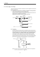
While pressing the installation lever located at the bottom of module, insert the module fixing tab into
the fixing hole in the base unit until it stops. Then, securely install the module with the fixing hole as a
supporting point. Incorrect installation of the module can cause an operation failure, failure or drop.
When using the Motion controller in the environment of much vibration, tighten the module with a screw.
Tighten the screw in the specified torque range. Under tightening may cause a drop, short circuit or
operation failure. Over tightening may cause a drop, short circuit or operation failure due to damage to
the screw or module.
Be sure to connect the extension cable to connectors of the base unit correctly. After connecting,
check them for looseness. Poor connections could cause an input or output failure.
Completely turn off the externally supplied power used in the system before installation or removing
the module. Not doing so could result in electric shock or damage to the product.
Do not install/remove the module onto/from base unit or terminal block more than 50 times, after the
first use of the product. Failure to do so may cause the module to malfunction due to poor contact of
connector.
Do not directly touch the module's conductive parts and electronic components. Touching them
could cause an operation failure or give damage to the module.
This section describes instructions for handling the CPU, I/O, intelligent function and
power supply modules, base units and so on.
(1) Module, terminal block connectors and pin connectors are made of resin; do not
drop them or subject them to strong impact.
(2) Do not remove modules' printed circuit boards from the enclosure in order to avoid
changes in operation.
(3) Tighten the module fixing screws and terminal block screws within the tightening
torque range specified below.
Location of screw Tightening torque range
Motion CPU module fixing screw (M3 13 screw) 0.36 to 0.48 N•m
Module fixing screw (M3 12 screw) 0.36 to 0.48 N•m
I/O module terminal block screw (M3 screw) 0.42 to 0.58 N•m
I/O module terminal block fixing screw (M3.5 screw) 0.68 to 0.92
N•m
Power supply module terminal screw (M3.5 screw) 0.68 to 0.92
N•m
4