
Instruction manual


4 - 57
4 POSITIONING DEDICATED SIGNALS
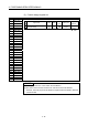
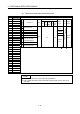
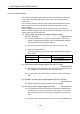
(6) Cam axis monitor device list
Axis No. Device No. Signal name
1 D1240 to D1249
2 D1250 to D1259
3
D1260 to D1269
Signal name Real Virtual
Refresh
cycle
Fetch cycle
Signal
direction
4 D1270 to D1279 0 Unusable
5 D1280 to D1289
1 Execute cam No.
6 D1290 to D1299 2
7 D1300 to D1309 3
Execute stroke amount
8 D1310 to D1319 4
9 D1320 to D1329 5
Current value within 1 cam shaft
revolution
Backup
Operation
cycle
Monitor
device
10 D1330 to D1339 6
11 D1340 to D1349
7
12 D1350 to D1359 8
13 D1360 to D1369
9
Unusable
14 D1370 to D1379 : Valid
15 D1380 to D1389
16 D1390 to D1399
17 D1400 to D1409
18 D1410 to D1419
19 D1420 to D1429
20 D1430 to D1439
21 D1440 to D1449
22 D1450 to D1459
23 D1460 to D1469
24 D1470 to D1479
25 D1480 to D1489
26 D1490 to D1499
27 D1500 to D1509
28 D1510 to D1519
29 D1520 to D1529
30 D1530 to D1539
31 D1540 to D1549
32 D1550 to D1559
POINT
(1) The range of axis No.1 to 8 is valid in the Q172DCPU.
(2) The unused axis areas in the mechanical system program can be used as an
user side.