
Instruction manual


4 - 51
4 POSITIONING DEDICATED SIGNALS
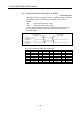
4.2 Data Registers
(1) Data register list
Q173DCPU Q172DCPU
Device No. Purpose Real Virtual Device No. Purpose Real Virtual
D0 D0
to
Axis monitor device
(20 points
8 axes)
Real mode ........... Each axis
Virtual mode ........ Output module
D160
to
Axis monitor device
(20 points
32 axes)
Real mode ........... Each axis
Virtual mode ........ Output module
to
Unusable
(480 points)
D640 D640
to
Control change register
(2 points
8 axes)
D656
to
Control change register
(2 points
32 axes)
to
Unusable
(48 points)
D704 D704
to
Common device
(Command signal)
(54 points)
to
Common device
(Command signal)
(54 points)
D758 D758
to
Unusable
(42 points)
to
Unusable
(42 points)
D800 D800
Virtual servomotor axis monitor
device
(6 points
32 axes)
(Note-1)
Virtual servomotor axis monitor
device
(6 points
8 axes)
(Note-1)
to
Current value after virtual
servomotor axis main shaft's
differential gear
(4 points
8 axes)
(Note-1)
Back
up
D880
Current value after virtual
servomotor axis main shaft's
differential gear
(4 points
32 axes)
(Note-1)
to
Unusable
(240 points)
D1120 D1120
Synchronous encoder axis
monitor device
(6 points
12 axes)
Synchronous encoder axis
monitor device
(6 points
8
axes)
to
Current value after synchronous
encoder axis main shaft's
differential gear
(4 points
8 axes)
Back
up
D1200
to
Current value after synchronous
encoder axis main shaft's
differential gear
(4 points
12 axes)
to
Unusable
(40 points)
D1240 D1240
to
Cam axis monitor device
(10 points
8 axes)
(Note-1)
Back
up
D1320
to
Cam axis monitor device
(10 points
32 axes)
(Note-1)
Back
up
to
Unusable
(6872 points)
D1560 D1560
to to
D8191
User device
(6632 points)
D8191
User device
(6632 points)
Usable in the user device.
: Valid
Real/
virtual
community
Virtual