
Instruction manual


4 - 45
4 POSITIONING DEDICATED SIGNALS
REMARK
(Note) : Refer to the "Q173DCPU/Q172DCPU User's Manual" for P1 to P3
connector of the Q173DPX.
(17) Operation cycle over flag (M2054) .................…....... Status signal
This flag turns on when the time concerning motion operation exceeds the
operation cycle of the Motion CPU setting (SD523). Perform the following
operation, in making it turn off.
• Turn the power supply of the Multiple CPU system on to off
• Reset the Multiple CPU system
• Reset using the user program
[Error measures]
1) Change the operation cycle into a large value in the system setting.
2) The number of instruction completions of an event task or NMI task in
the Motion SFC program.
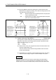
(18) Speed changing accepting flag (M2061 to M2092)
................... Status signal
This flag turns on during speed change by the control change (CHGV)
instruction (or Motion dedicated PLC instruction (D(P).CHGV)) of the Motion
SFC program.
CHGV instruction
Speed changing
accepting flag
Setting speed
OFF
ON
Speed change
Speed change completion
Speed after
speed change
0 to 4ms
t
The speed changing accepting flag list is shown below.
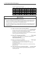
Axis No. Device No. Axis No. Device No. Axis No. Device No. Axis No. Device No.
1 M2061 9 M2069 17 M2077 25 M2085
2 M2062 10 M2070 18 M2078 26 M2086
3 M2063 11 M2071 19 M2079 27 M2087
4 M2064 12 M2072 20 M2080 28 M2088
5 M2065 13 M2073 21 M2081 29 M2089
6 M2066 14 M2074 22 M2082 30 M2090
7 M2067 15 M2075 23 M2083 31 M2091
8 M2068 16 M2076 24 M2084 32 M2092
(Note) : The range of axis No.1 to 8 is valid in the Q172DCPU.