
Instruction manual


4 - 6
4 POSITIONING DEDICATED SIGNALS
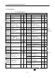
(3) Axis command signal list
Axis No. Device No. Signal name
1 M3200 to M3219
2 M3220 to M3239 Virtual
3 M3240 to M3259
4 M3260 to M3279
5 M3280 to M3299
Signal name Real
Roller
Ball
screw
Rotary
table
Cam
Real
mode
axis
Refresh
cycle
Fetch
cycle
Signal
direction
6 M3300 to M3319 0 Stop command
7 M3320 to M3339 1 Rapid stop command
Operation
cycle
8 M3340 to M3359
9 M3360 to M3379
2
Forward rotation JOG
start command
10 M3380 to M3399
11 M3400 to M3419
3
Reverse rotation JOG
start command
12 M3420 to M3439
13 M3440 to M3459
4
Complete signal OFF
command
Main
cycle
14 M3460 to M3479
15 M3480 to M3499
5
Speed/position switching
enable command
Operation
cycle
Command
signal
16 M3500 to M3519 6 Unusable
17 M3520 to M3539 7 Error reset command
18 M3540 to M3559
19 M3560 to M3579
8
Servo error reset
command
Main
cycle
20 M3580 to M3599
21 M3600 to M3619
9
External stop input
disable at start command
At start
Command
signal
22 M3620 to M3639 10
23 M3640 to M3659 11
Unusable
24 M3660 to M3679
25 M3680 to M3699
12
Feed current value
update request command
At start
26 M3700 to M3719
27 M3720 to M3739
13
Address clutch reference
setting command
(Note-1)
28 M3740 to M3759
29 M3760 to M3779
14
Cam reference position
setting command
(Note-1)
At virtual
mode
transition
30 M3780 to M3799
31 M3800 to M3819
15 Servo OFF command
Operation
cycle
32 M3820 to M3839
16 Gain changing command
Operation
cycle
(Note-2)
Command
signal
17 Unusable
18
Control loop changing
command
19 FIN signal
Operation
cycle
Command
signal
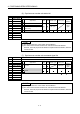
: Valid, : Invalid
(Note-1) : It is unusable in the SV22 real mode.
(Note-2) : Operation cycle 7.1[ms] or more: Every 3.5[ms]
POINT
(1) The range of axis No.1 to 8 is valid in the Q172DCPU.
(2) The device area more than 9 axes as an user device in the Q172DCPU.
However, when the project of Q172DCPU is replaced with Q173DCPU, this area
cannot be used.