
Instruction manual


APP - 62
A
PPENDICES
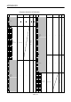
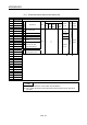
(11) Virtual servomotor axis monitor device list
Axis No. Device No. Signal name
1 D800 to D809
2 D810 to D819 Virtual
3 D820 to D829
4 D830 to D839
5 D840 to D849
Signal name Real
Roller
Ball
screw
Rotary
table
Cam
Real
mode
axis
Refresh
cycle
Fetch
cycle
Signal
direction
6 D850 to D859 0
7 D860 to D869
1
Feed current value
Operation
cycle
8 D870 to D879 2 Minor error code
9 D880 to D889 3 Major error code
Immediately
10 D890 to D899 4 Execute program No. At start
11 D900 to D909
12 D910 to D919
5 M-code
13 D920 to D929
6
14 D930 to D939
15 D940 to D949
7
Current value after virtual
servomotor axis main
shaft's differential gear
16 D950 to D959
8 Error search output axis No.
17
D960 to D969
18 D970 to D979
9
Data set pointer for
constant-speed control
Backup
Operation
cycle
Monitor
device
19 D980 to D989 : Valid, : Invalid
20 D990 to D999
21 D1000 to D1009
22 D1010 to D1019
23 D1020 to D1029
24 D1030 to D1039
25 D1040 to D1049
26 D1050 to D1059
27 D1060 to D1069
28 D1070 to D1079
29
D1080 to D1089
30 D1090 to D1099
31 D1100 to D1109
32 D1100 to D1119
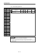
POINT
(1) The range of axis No.1 to 8 is valid in the Q172DCPU.
(2) The unused axis areas in the mechanical system program can be used as an
user side.