
Instruction manual


APP - 60
A
PPENDICES
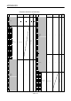
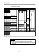
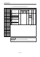
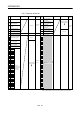
(9) Axis monitor device list
Axis No. Device No. Signal name
1 D0 to D19
2 D20 to D39 Virtual
3 D40 to D59
4 D60 to D79
5 D80 to D99
Signal name Real
Roller
Ball
screw
Rotary
table
Cam
Real
mode
axis
Refresh
cycle
Fetch
cycle
Signal
direction
6 D100 to D119 0
7 D120 to D139 1
Feed current
value/roller cycle speed
8 D140 to D159 2
9 D160 to D179 3
Real current value
10 D180 to D199 4
11 D200 to D219 5
Deviation counter value
Operation
cycle
12 D220 to D239
6 Minor error code
13 D240 to D259 7 Major error code
Immediately
14 D260 to D279
8 Servo error code
Main cycle
15 D280 to D299
16
D300 to D319
9
Home position return
re-travel value
Backup
17 D320 to D339 10
18 D340 to D359
11
Travel value after
proximity dog ON
Backup
Operation
cycle
19 D360 to D379 12 Execute program No. At start
20 D380 to D399 13 M-code
21 D400 to D419 14 Torque limit value
Operation
cycle
22 D420 to D439
23 D440 to D459
15
Data set pointer for
constant-speed control
At start/
during start
Monitor
device
24 D460 to D479 16
25 D480 to D499 17
Unusable
(Note-1)
26 D500 to D519 18
27 D520 to D539
19
Real current value at
stop input
Backup
Operation
cycle
Monitor
device
28 D540 to D559 : Valid, : Invalid
29 D560 to D579
30 D580 to D599
31 D600 to D619
32 D620 to D639
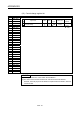
(Note-1): It can be used as the travel value change register. The travel value change register can be set to the device optionally in the servo
program.
Refer to the "Q173DCPU/Q172DCPU Motion controller (SV13/SV22) Programming Manual (REAL MODE)" for details.
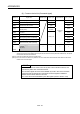
POINT
(1) The range of axis No.1 to 8 is valid in the Q172DCPU.
(2) The device area more than 9 axes as an user device in the Q172DCPU.
However, when the project of Q172DCPU is replaced with Q173DCPU, this area
cannot be used.