
Instruction manual


9 - 4
9 REAL MODE/VIRTUAL MODE SWITCHING AND STOP/RE-START
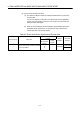
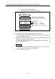
(3) Synchronous encoder axis check
(a) The items in Table 9.3 below are checked to determine the synchronous
encoder state.
If an error is detected, it switches to the virtual mode, but the applicable
system cannot be started. Correct the error cause in the real mode, and
switch to virtual mode again.
(b) When an error is detected, the error detection signal (M2407+20n) of the
applicable output module turns on, and the error code is stored in the
minor/major error code storage register.
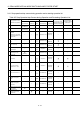
Table 9.3 Check Items List for Synchronous Encoder Axis
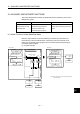
Applicable synchronous
encoder
Check sequence Check item
External
synchronous
encoder
Output
module
Normal
condition
Abnormal
condition
Not connected
1
• Is the synchronous encoder connected
to the Q172DEX ?
— Connected
Cable break