
Instruction manual


8 - 40
8 OUTPUT MODULE
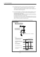
8.5 Phase Compensation Function
When carrying out a position follow-up control (synchronous operation) by
synchronous encoder, delays in the progresses, etc. cause the phase to deviate at
servomotor shaft end in respect to the synchronous encoder. The phase compensation
function compensates in this case so that the phase does not deviate.
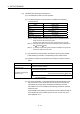
(1) Parameter list
Set the following devices for axes to execute the phase compensation function.
(Set in the output module parameter.)
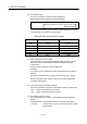
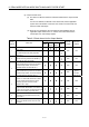
Table 8.7 Phase Compensation Function Parameter List
No. Item Device setting range Setting range
1
Phase advance time
(2 words)
D0 to D8191
(Note-1), (Note-2)
W0 to W1FFF
(Note-2)
U \G10000 to U \G(10000+p-1)
(Note-2) , (Note-3)
-2147483648 to
2147483647[µs]
2
Phase compensation
time constant
(1 word)
D0 to D8191
(Note-1)
W0 to W1FFF
U
\G10000 to U \G(10000+p-1)
(Note-3)
0 to 32767[times]
3
Phase compensation
processing valid flag
X0 to X1FFF
Y0 to Y1FFF
M0 to M8191
(Note-4)
F0 to F2047
B0 to B1FFF
U
\G10000.0 to U \G(10000+p-1).F
(Note-3)
—
4
Compensation amount
monitor device
(2 words)
D0 to D8191
(Note-1), (Note-2)
W0 to W1FFF
(Note-2)
U
\G10000 to U \G(10000+p-1)
(Note-2), (Note-3), (Note-5)
—
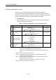
(Note-1) : D800 to D1559 are dedicated devices of virtual servomotor axis, synchronous
encoder axis and output module "Cam" in the virtual mode.
Unused areas of virtual servomotor axis and cam axis can be used as an user
device.
(Note-2) : Set an even number at the first device.
(Note-3) : "p" indicates the user setting area points of the Multiple CPU high speed
transmission area for the each CPU.
(Note-4) : "M4000 to M4639 and M4800 to M5439" are the dedicated devices of virtual
servomotor axis in the virtual mode.
Unused area of virtual servomotor axis can be used as an user side.
(Note-5) : Only device of the self CPU can be used.