
Instruction manual


8 - 37
8 OUTPUT MODULE
(11) Cam/ball screw switching command device
(a) This parameter is used to set cam operation.
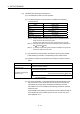
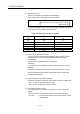
(b) The following devices can be used as the cam/ball screw switching
command device.
Name Setting range
Input X0 to X1FFF
Output Y0 to Y1FFF
Internal relay M0 to M8191
(Note-1), (Note-2)
Link relay B0 to B1FFF
Annunciator F0 to F2047
Multiple CPU area device U \G10000.0 to U \G(10000+p-1).F
(Note-3)
(Note-1) : "M4000 to M4639 and M4800 to M5439" are the dedicated devices of
virtual servomotor axis in the virtual mode.
Unused area of virtual servomotor axis can be used as an user side.
(Note-2) : Use these parameters to use the device (M5488 to M5519) allocated to
Q17
CPUN/Q17 HCPU.
(Note-3) : "p" indicates the user setting area points of the Multiple CPU high speed
transmission area for the each CPU.
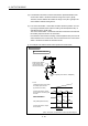
(c) Cam executes the same operation as ball screw by turning the cam/ball
screw switching command on corresponding to each output axis No..
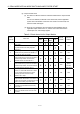
(d) Operation of output axis by cam/ball screw switching command is shown
below.
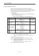
Items Operation details
Cam/ball screw switching
command : OFF
Specified cam pattern operation
Same operation as ball screw
Command to servo amplifier = Preset command to servo amplifier +
Drive module travel value[PLS]
Gear ratio
Cam/ball screw switching
command : ON
(Note): Feed current value is calculated based on the travel value per pulse set
in the fixed parameter.
(e) The current value within 1 cam shaft revolution is calculated based on the
feed current value, lower stroke limit value, stroke amount and cam No.
(cam pattern) by turning off the cam/ball screw switching command.
It is invalid to turn on the cam/ball screw switching command to axis that
except cam axis.
If the cam/ball screw switching command is turned off outside the range of
"lower stroke limit value to stroke amount" for cam, a minor error (error
code: 5000) will occur.