
Instruction manual


8 - 36
8 OUTPUT MODULE
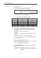
(d) The address mode clutch is turned on/off with the specified address of the
current value within 1 virtual axis revolution range of 0 to (N
C-1) [PLS].
Therefore, set the address value within the range of 0 to (N
C-1) [PLS] in the
clutch ON/OFF address setting device.
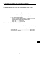
(e) The current value within 1 virtual axis revolution reference position "0" is set
by turning the address clutch reference setting command (M3213+20n) on
and switching to the virtual mode.
The current values within 1 virtual axis revolution for both the main shaft and
the auxiliary input axis is set to "0" at this time.
If the address clutch reference setting command (M3213+20n) is turned off
and it switches to the virtual mode, control continues from the current value
within 1 virtual axis revolution of last virtual mode.
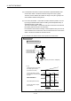
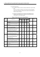
(f) An example of an address mode clutch operation is shown below.
100000 00
20000
0
0 0
20000
2 axes
Number of pulses per revolution : 20000[PLS]
Cam
2 axes
Set the clutch status
Clutch ON address = 0
Cam pattern(Stroke amount)
Current value within 1 output
axis revolution
Main shaft side clutch OFF
Set the clutch ON/OFF
in this current value.
(Current value within 1
virtual axis revolution)
Virtual servomotor current value
of auxiliary input axis side
(Synchronous encoder)
Current value within 1 virtual
axis revolution of auxiliary input
axis side
(Note): The rotation of output axis is reversed by differential gear.
Operation example