
Instruction manual


8 - 33
8 OUTPUT MODULE
(c) The lower stroke limit value is range of -2147483648 (-2
31
) to 2147483647
(2
31
-1).
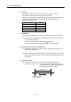
1) The lower stroke limit value is determined as follows for each unit setting:
[mm]: Lower stroke limit value
10
-1
[µm]
[inch]: Lower stroke limit value
10
-5
[inch]
[PLS]: Lower stroke limit value
1 [PLS]
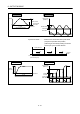
(9) Current value within 1 virtual axis revolution storage device
(Main shaft side) (2 words)
This parameter is set when the address mode clutch is set at the cam main shaft
side.
0000
Drive module
Current value within 1 virtual
axis revolution
Address mode clutch
Cam
(Nc-1)
PLS
Current value within 1 virtual axis revolution
= (Drive module travel value gear) %Nc
(% : Remainder operator)
(a) The current value within 1 virtual axis revolution of cam main shaft side is
stored in the preset device.
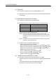
(b) The following devices can be set as the current value within 1 virtual axis
revolution storage device.
Name Setting range
(Note-1)
Data register D0 to D8191
(Note-2)
Link register W0 to W1FFF
Motion register #0 to #7999
Multiple CPU area device
U
\G10000 to U \G(10000+p-1)
(Note-3), (Note-4)
(Note-1) : Set an even number at the first device.
(Note-2) : D800 to D1559 are dedicated devices of the virtual servomotor axis,
synchronous encoder axis and output module "Cam" in the virtual mode.
The unused areas of the virtual servomotor axis and cam axis can be used
as a user device.
(Note-3) : "p" indicates the user setting area points of the Multiple CPU high speed
transmission area for the each CPU.
(Note-4) : Only device of the self CPU can be used.
(c) The current value within 1 virtual axis revolution is the range of 0 to (N
C-1)
[PLS].
(N
C: Number of pulses per cam shaft revolution)