
Instruction manual


8 - 3
8 OUTPUT MODULE
POINT
(1) Be sure to set an even-numbered device for the items set as 2-word. And, when
the data is set to device in the Motion SFC program, set it as 32-bit integer type.
(2) When a 2-word monitor device is read in the Motion SFC program, read it as
32-bit integer type.
(3) Refer to Chapter 2 of the "Q173DCPU/Q172DCPU Motion controller
Programming Manual (COMMON)" for the user setting area points of the
Multiple CPU high speed transmission area.
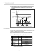
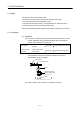
(b) Device data input
All indirect setting device data are input as "initial value" at the switching real
mode/virtual mode, thereafter the input control for module is executed during
the virtual mode operation.
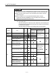
The input timing and refresh cycle of setting device are shown below.
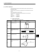
Device input timing
Module Item
Input
device
Refresh
device
Real mode
/Virtual mode
switching
During the Virtual
mode operation
Refresh
cycle
Roller Torque limit value setting device
Ball screw Torque limit value setting device
Torque limit value setting device
Input for every
operation cycle.
(Note)
Current value within 1 virtual axis
revolution storage device
(Main shaft side)
Rotary table
Current value within 1 virtual axis
revolution storage device
(Auxiliary input axis side)
Operation
cycle
(Note)
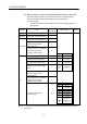
Cam No. setting device
Stroke amount setting device
Input for every
operation cycle.
(Note)
However, the cam
No. and stroke
amount switching
position pass point
are valid.
Torque limit value setting device
Input for every
operation cycle.
(Note)
Lower stroke limit value storage
device
Current value within 1 virtual axis
revolution storage device
(Main shaft side)
Current value within 1 virtual axis
revolution storage device
(Auxiliary input axis side)
Operation
cycle
(Note)
Cam
Cam/ball screw switching
command device
Input for every
operation cycle.
(Note)