
Instruction manual


8 - 2
8 OUTPUT MODULE
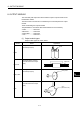
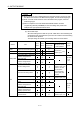
(2) Device range of output module parameters and device data input
The device range and setting method of items set in the indirect setting by
devices among the output module parameters are shown below.
(a) Device range
The number of device words and device range in the indirect setting are
shown below.
Module Item
Number of
device words
Device range Remark
Roller Torque limit value setting device 1
Ball screw Torque limit value setting device 1
Torque limit value setting device 1
Current value within 1 virtual axis
revolution storage device
(Main shaft side)
2
Rotary table
Current value within 1 virtual axis
revolution storage device
(Auxiliary input axis side)
2
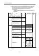
Device Range
Cam No. setting device 1 D
0 to 8191
Stroke amount setting device 2 W
0 to 1FFF
Torque limit value setting device 1 # 0 to 7999
Lower stroke limit value storage
device
2 U
\G
10000 to
(10000+p-1)
(Note-1)
Current value within 1 virtual axis
revolution storage device
(Main shaft side)
2
Current value within 1 virtual axis
revolution storage device
(Auxiliary input axis side)
2
Device Range
X 0 to 1FFF
Y 0 to 1FFF
M 0 to 8191
B 0 to 1FFF
F 0 to 2047
U \G
10000.0 to
(10000+p-1).F
(Note-1)
Cam
Cam/ball screw switching
command device
Bit
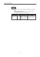
(Note-1) : "p" indicates the user setting area points of the Multiple CPU high speed transmission area for
the each CPU.