
Instruction manual


7 - 27
7 TRANSMISSION MODULE
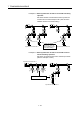
(3) Clutch ON/OFF command device
(a) This device is used to execute the clutch ON/OFF command.
(b) The following devices can be used as the clutch ON/OFF command device.
Name Setting range
Input X0 to X1FFF
Output Y0 to Y1FFF
Internal relay M0 to M8191
(Note-1)
Link relay B0 to B1FFF
Annunciator F0 to F2047
Multiple CPU area device U \G10000.0 to U \G(10000+p-1).F
(Note-2)
(Note-1) : "M4000 to M4639 and M4800 to M5439" are the dedicated devices of
virtual servomotor axis in the virtual mode.
Unused area of virtual servomotor axis can be used as an user side.
(Note-2) : "p" indicates the user setting area points of the Multiple CPU high speed
transmission area for the each CPU.
(4) Clutch status
(a) This device is used to indicate the clutch ON/OFF state.
(b) The following devices can be used as the clutch status.
Name Setting range
Input X0 to X1FFF
Output Y0 to Y1FFF
Internal relay M0 to M8191
(Note-1), (Note-2)
Link relay B0 to B1FFF
Annunciator F0 to F2047
Multiple CPU area device
U
\G10000.0 to U \G(10000+p-1).F
(Note-3), (Note-4)
(Note-1) : "M4000 to M4639 and M4800 to M5439" are the dedicated devices of
virtual servomotor axis in the virtual mode. Unused area of virtual
servomotor axis can be used as an user side.
(Note-2) : Use these parameters to use the device (M2160 to M2223) allocated to
Q17
CPUN/Q17 HCPU.
(Note-3) : "p" indicates the user setting area points of the Multiple CPU high speed
transmission area for the each CPU.
(Note-4) : Only device of the self CPU can be used.