
Instruction manual


7 - 26
7 TRANSMISSION MODULE
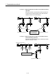
(b) If a synchronous encoder is used as the drive module, the operation modes
that can be set differ depending on the encoder interface connected to the
Q173DPX/Q172DEX.
Clutch operation mode
Encoder interface
ON/OFF mode
Address mode,
Address mode 2,
One-Shot mode
External input
mode
Manual pulse generator input (INC)
Serial encoder input (ABS)
: Enable, : Disable
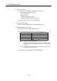
(2) Mode setting device (only ON/OFF mode, address mode, address mode 2 and
one-shot mode combined use, 1 word)
(a) This device is used to switch the ON/OFF mode and address mode.
The mode by mode setting device value are as follows:
Mode setting device No. Name
0 ON/OFF mode
1 Address mode
2 Address mode 2
3, 4 One-shot mode
`The mode setting device of except for "0 to 4" is regarded as an error, and
an operation is continued at the previous setting value.
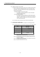
(b) The following devices can be used as the mode setting device.
Name Setting range
Data register D0 to D8191
(Note-1)
Link register W0 to W1FFF
Motion register #0 to #7999
Multiple CPU area device U \G10000 to U \G(10000+p-1)
(Note-2)
(Note-1) : D800 to D1559 are dedicated devices of virtual servomotor axis,
synchronous encoder axis and output module "cam" in the virtual mode.
Unused areas of virtual servomotor axis and cam axis can be used as an
user device.
(Note-2) : "p" indicates the user setting area points of the Multiple CPU high speed
transmission area for the each CPU.