
Instruction manual


7 - 1
7
7 TRANSMISSION MODULE
7. TRANSMISSION MODULE
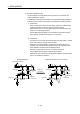
The transmission module transmits the pulse outputted from the drive module to output
module.
There are following 4 types transmission modules.
• Gear .................................. Section 7.1
• Clutch ................................ Section 7.2
• Speed change gear .......... Section 7.3
• Differential gear ................ Section 7.4
The device range and setting procedure for indirect setting in the parameter setting of
the transmission module are show below.
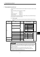
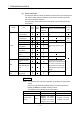
(1) Device range
The number of device words and device range at the indirect setting are shown
below.
Module Item
Number of
device words
Device setting range Remark
Device Range
Clutch ON/OFF command device
X 0000 to 1FFF
Y 0000 to 1FFF
M 0 to 8191
Smoothing clutch complete signal
B 0000 to 1FFF
F 0 to 2047
U
\G
10000.0 to
(10000+p-1).F
(Note-1)
Clutch status
Bit
Mode setting device 1
Clutch ON address setting device 2
Device Range
Clutch OFF address setting device 2 D 0 to 8191
Slippage setting device 2 W 0000 to 1FFF
# 0 to 7999
Clutch
Slippage in-position range setting
device
2
Input axis side tooth count 1
U
\G
10000 to
(10000+p-1)
(Note-1)
Gear
Output axis side tooth count 1
Speed change gear Speed change ratio setting device 1
(Note-1) : "p" indicates the user setting area points of the Multiple CPU high speed transmission area for the each CPU.
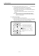
POINT
(1) Be sure to set an even-numbered device for the items set as 2-word. And, when
the data is set to device in the Motion SFC program, set it as 32-bit integer type.
(2) When a 2-word monitor device is read in the Motion SFC program, read it as
32-bit integer type.
(3) Refer to Chapter 2 of the "Q173DCPU/Q172DCPU Motion controller
Programming Manual (COMMON)" for the user setting area points of the
Multiple CPU high speed transmission area.