
Instruction manual


6 - 21
6 DRIVE MODULE
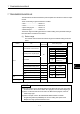
6.2.2 Parameter list
The synchronous encoder parameters are shown in Table 6.2 and the parameters
shown in this table are explained in items (1) below.
Refer to the help of MT Developer for the parameter setting method of synchronous
encoder.
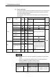
Table 6.2 Synchronous Encoder Parameter List
No. Setting item Default value Setting range
1 Synchronous encoder No. —
Q173DCPU : 1 to 12
Q172DCPU : 1 to 8
2 Error-time operation mode Continuation Continuation/ Clutch OFF
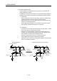
(1) Synchronous encoder No.
The synchronous encoder No. is set connected to the Q172DEX/Q173DPX.
Connecting position of Q172DEX/Q173DPX Synchronous encoder No.
P1/E1 1
P2/E2 2
P3/E3 3
P4/E4 4
P5/E5 5
P6/E6 6
P7/E7 7
P8/E8 8
P9/E9 9
P10/E10 10
P11/E11 11
P12/E12 12
P1 to P12: Connect to the Q173DPX.
This is incremental type synchronous encoders.
E1 to E12: Connect to the Q172DEX.
This is absolute synchronous encoder.
REMARK
(Note-1) : The absolute and incremental synchronous encoders can be
used (set) together.
(Note-2) : The synchronous encoder No.1 to 8 are valid in the Q172DCPU.