
Instruction manual


6 - 17
6 DRIVE MODULE
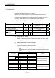
6.2 Synchronous Encoder
The synchronous encoder is used to operate the virtual axis (virtual main shaft, virtual
auxiliary input axis) with the external input pulse.
Synchronous encoder operation and parameters are shown below.
6.2.1 Operation description
(1) Operations
Although a synchronous encoder does not need to start using the servo program
etc. in order to operate it by external devices, it needs cautions for the timing
which begins to input the input pulse from a synchronous encoder.
The input timing from a synchronous encoder is shown below.
(a) Operation start
The input timing of input pulse from an external synchronous encoder is
shown below.
• At the switching from real mode to virtual mode
• At the external signal
(Note-2)
(TREN : Synchronous encoder input start
signal) input
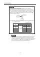
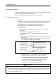
1) When the input pulse is started to input at the switching from real mode
to virtual mode.
a) The input pulse is inputted from the external synchronous encoder at
the switching from real mode to virtual mode.
Real mode/virtual mode
(Note-1)
switching request flag (M2043)
OFF
ON
OFF
ON
(-2
31
)
Real mode
Real mode/virtual mode
(Note-1)
switching status flag (M2044)
Input pulse from the external
synchronous encoder
Feed current value of the
synchronous encoder axis
Virtual mode
(2
31
-1)
Operation start of the synchronous encoder axis
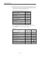
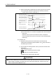
b) The control mode
(Note-3)
of a clutch is operation in the case of
ON/OFF mode and address mode. It can be used with the
synchronous encoder for the incremental/absolute data method.
c) It depends on the state of connected clutch whether synchronous
encoder operation is transmitted or not to the output module.
• Clutch ON ........ Transmit to the output module.
• Clutch OFF ...... Not transmit to the output module.
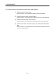
CAUTION
If the mode is switched from real mode to virtual mode in the state of clutch ON, use the smoothing
clutch. If the direct clutch is used and the mode is switched from real mode to virtual mode in the state
of clutch ON, the rapid acceleration occurs at the output module axis, causing a servo error, and the
machine will be subjected to a jolt.