
Instruction manual


6 - 11
6 DRIVE MODULE
6.1.2 Parameter list
The virtual servomotor parameters are shown in Table 6.1 and the parameters shown
in this table are explained in items (1) to (4) below.
Refer to the help of MT Developer for the parameter setting method of virtual
servomotor.
A parameter is requested except for the above for program operation of the virtual
servomotor. Refer to the item (5) for precautions of the parameter blocks.
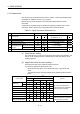
Table 6.1 Virtual Servomotor Parameter List
No. Setting item Default value Setting range
1 Virtual axis No.
Q173DCPU : 1 to 32
Q172DCPU : 1 to 8
2 Upper stroke limit value 2147483647 PLS -2147483648 to 2147483647 PLS
3 Lower stroke limit value 0 PLS -2147483648 to 2147483647 PLS
4 Command in-position range 100 PLS 1 to 32767 PLS
5 JOG speed restriction 200000 PLS/s 1 to 2147483647 PLS/s
6
JOG operation-time
parameter
Parameter block No. 1
1 to 64
7 Operation mode at error occurrence Continuation
Continuation/Clutch OFF
(1) Virtual axis No. setting
The virtual axis No. is set in the servo program at the virtual mode operation. The
axis No. of the virtual servomotor connected to the virtual main shaft or virtual
auxiliary input axis.
(2) Upper/lower stroke limit value settings
The stroke limit range of the virtual servomotor axis is set.
(a) When the stroke limit value is made valid:
Set the stroke range of the "Lower stroke limit value < upper stroke limit
value".
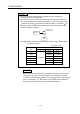
The stroke limit check and control details at the start/during start are shown
below.
Error check
(Note)
At start During start
Control mode
106 207 208 220
Remarks
Linear
Positioning
Circular
Fixed-pitch feed
Speed-switching
Constant-speed/Helical
Position follow-up
Start in the return direction in a
stroke limit range from outside the
stroke limit range is possible.
Speed
Stroke limit is invalid.
JOG
Manual pulse generator
Start in the return direction in a
stroke limit range from outside the
stroke limit range is possible.
(Note) : Code detected at the error check.