
Instruction manual


5 - 5
5 MECHANICAL SYSTEM PROGRAM
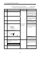
5.2 Mechanical Module List
An overview of the mechanical modules used at the mechanical module connection
diagrams in the virtual mode is shown in Tables 5.1.
Refer to Chapter 6 to 8 for details of the each mechanical module.
Table 5.1 Mechanical Module List
Maximum Number of Usable
Mechanical Module
Q173DCPU Q172DCPU
Number Per Block Number Per Block
Classifi-
cation
Name Appearance
Number
Per
Motion
CPU
module
Number
Per
System
Connection
Shaft Side
Auxiliary
Input
Axis Side
Number
Per
Motion
CPU
module
Number
Per
System
Connection
Axis Side
Auxiliary
Input
Axis Side
Function Description Section
Virtual
servomotor
32 32
–- –-
88
–- –-
• It is used to drive the virtual axis of
mechanical system program by the
servo program or JOG operation.
Section
6.1
Drive
module
Synchronous
encoder
12
Total
44
12
Total
34
–- –-
8
Total
16
8
Total
10
–- –-
• It is used to drive the virtual axis by the
input pulses from the external
synchronous encoder.
Section
6.2
Virtual main
shaft
–-
32 32
–- –-
88
–- –-
• This is a virtual "link shaft".
• Drive module rotation is transferred to
the transmission module.
–-
Virtual
axis
Virtual
auxiliary
input axis
–-
32
Total
64
32
–- –-
8
Total
16
8
–- –-
• This is the auxiliary input axis for input to
the differential gear of transmission
module.
• It is automatically displayed when a
differential gear and gear are connected.
–-
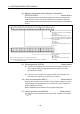
Gear
64 64 1 1 16 16 1 1
• The drive module rotation is transmitted
to the output axis.
• A setting gear ratio is applied to the
travel value (pulse) input from the drive
module, and then transmits to the output
axis that it becomes in the setting
rotation direction.
Section
7.1
Direct clutch
Smoothing
clutch
64 64 1 1 16 16 1 1
• Transmit or separate the drive module
rotation to the output module.
• There are a direct clutch transmitted
directly and the smoothing clutch which
performs the acceleration/deceleration
and transmission by the smoothing time
constant setting at the switching
ON/OFF of the clutch.
• It can be selected the ON/OFF mode,
address mode or the external input
mode depending on the application.
• Time constant system or slippage
system can be selected as a smoothing
method.
Section
7.2
Speed change
gear
64 64 1 1 16 16 1 1
• It is used to change the speed of output
module (roller).
• The setting speed change ratio is
applied to input axis speed, and
transmits to the output axis.
Section
7.3
32 32 1 8 8 1
• Auxiliary input axis rotation is
subtracted from virtual main shaft
rotation and the result is transmitted to
the output axis.
Trans-
mission
module
Differential
gear
32 1
–-
–-
8 1
–-
–-
• Auxiliary input axis rotation is
subtracted from virtual main shaft
rotation, and the result is transmitted to
the output axis.
(Connected to the virtual main shaft)
Section
7.4
Roller
32 32 8 8
• It is used to perform the speed control
at the final output.
Section
8.1
Ball
screw
32 32 8 8
• It is used to perform the linear
positioning control at the final output.
Section
8.2
Rotary
table
32 32 8 8
• It is used to perform the angle control
at the final output.
Section
8.3
Output
module
Cam
32
Total
32
32
Total
32
1 1
8
Total
8
8
Total
8
1 1
• It is used to control except the above.
Position control is executed based on
the cam pattern setting data.
• There are 2 cam control modes: the
two-way cam and feed cam.
Section
8.4