
Instruction manual


5 - 2
5 MECHANICAL SYSTEM PROGRAM
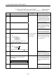
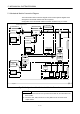
5.1 Mechanical Module Connection Diagram
The mechanical module connection diagram shows a virtual system diagram which
arranged the mechanical modules and was composed.
Configuration of the mechanical module connection is shown in Fig. 5.1 below.
Virtual
servomotor
Roller
Differential
gear
Gear
Speed
change gear
Clutch
Ball
screw
Rotary
table
Clutch
Indicates rotation direction
Virtual main shaft
input axis
1 system
1 block
Gear
Drive module Transmission module
Drive module
Virtual axis
Synchronous
encoder
Cam
Drive module
Output axis
Transmission module
Output module
Virtual auxiliary
Synchronous
encoder
Synchronous
encoder
Virtual
servomotor
Virtual
servomotor
Connection axis
Differential
gear
Speed
change gear
Fig. 5.1 Configuration of the Mechanical Module Connection
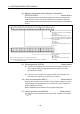
POINT
(1) Either a virtual servomotor or a synchronous encoder can be connected in the
drive module.
(2) One of the cam, roller, ball screw or rotary table can be connected in the
output module.