
Instruction manual


4 - 80
4 POSITIONING DEDICATED SIGNALS
(a) Servo amplifier mounting status
1) Mounting status
• Mounted ..…..... The servo amplifier is normal. (Communication with
the servo amplifier is normal.)
• Not mounted .... The servo amplifier is not mounted.
The servo amplifier power is off.
Normal communication with the servo amplifier is
not possible due to a connecting cable fault, etc.
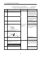
2) The system settings and servo amplifier mounting status are shown
below.
Servo amplifier
System Settings
Mounted Not mounted
Used (axis No. setting) 1 is stored 0 is stored
Unused 0 is stored
(4) Real mode/virtual mode switching error information
(SD504 to SD506) .........................….........…....….. Monitor device
When a mode switching error occurs in real-to-virtual or virtual-to-real mode
switching, or a mode continuation error occurs in the virtual mode, its error
information is stored.
Refer to APPENDIX 2.7 for details of the stored error code.
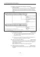
The axis error code among the error codes stored in SD504 to SD506 is shown
below.
Axis 16 Axis 15 Axis 14 Axis 13 Axis 12 Axis 11 Axis 10 Axis 9 Axis 8 Axis 7 Axis 6 Axis 5 Axis 4 Axis 3 Axis 2 Axis 1
Axis 32 Axis 31 Axis 30 Axis 29 Axis 28 Axis 27 Axis 26 Axis 25 Axis 24 Axis 23 Axis 22 Axis 21 Axis 20 Axis 19 Axis 18 Axis 17
b15 b0
SD505
SD506
SD504
Error
Erroneous axis bit "1"
<Example> For 8 axes error
(Decimal) "128" and (Hexadecimal) "0080H" is stored in the SD505,
(Decimal) "0" and (Hexadecimal) "0000H" is stored in the SD506,
and the error code is stored in the SD504.
(5) Connect/disconnect (status) (SD508) .......…........... Monitor device
This signal is used to temporarily suspend SSCNET communication while servo
amplifiers and/or SSCNET
cables after Axis 1 are exchanged with the power
supply ON in a Multiple CPU system.
SD508 stores the command status for "accept waiting" or "execute waiting"
during this process.
• 0 ………… Connect/disconnect command accept waiting
• -1 ……….. Connect/disconnect execute waiting
• -2 ………... Connect/disconnect executing
Refer to the "Q173DCPU/Q172DCPU Motion controller Programming Manual
(COMMON)" for details of the connect/disconnect function.