
Instruction manual


4 - 76
4 POSITIONING DEDICATED SIGNALS
(b) If the test mode is not executed in the test mode request from
MT Developer, the TEST mode request error flag (SM510) turns on.
(3) External forced stop input flag (SM502) ....………… Status signal
This flag is used to check the external forced stop input signal ON/OFF.
• OFF ........ External forced stop input ON
• ON ........ External forced stop input OFF
POINT
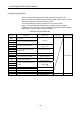
(1) If the forced stop signal is input during positioning, the feed current value is
advanced within the rapid stop deceleration time set in the parameter block.
At the same time, the servo OFF state is established because the all axes
servo ON command (M2042) turns off.
When the rapid stop deceleration time has elapsed after input of the forced
stop signal, the feed current value returns to the value at the point when the
emergency stop was initiated.
(2) If the forced stop is reset before the emergency stop deceleration time has
elapsed, a servo error occurs.
(4) Digital oscilloscope executing flag (SM503) .……...... Status signal
This flag is used to check the state of execution for the digital oscilloscope.
• 0 ........ Digital oscilloscope has stopped.
• 1 ........ Digital oscilloscope is executing.
(5) TEST mode request error flag (SM510) .........………. Status signal
(a) This flag turns on when the test mode is not executed in the test mode
request using MT Developer.
(b) When SM510 turns on, the error contents are stored in the test mode
request error information (SD510, SD511).
(6) Motion CPU WDT error flag (SM512) ......................... Status signal
This flag turns on when a "watchdog timer error" is detected of the Motion CPU
self-diagnosis function.
When the Motion CPU detects a WDT error, it executes an immediate stop
without deceleration of the operating axes.
If the Motion CPU WDT error flag has turn on, reset the Multiple CPU system.
If SM512 remains on after resetting, there is a fault at the Motion CPU side.
The error cause is stored in the "Motion CPU WDT error cause (SD512)".
(Refer to Section 4.5(7)).
(7) Manual pulse generator axis setting error flag (SM513)
.………...... Status signal
(a) This flag is use as judgement of normal or abnormal setting of the manual
pulse generator axis No. setting registers (D714 to D719).
• OFF ......... D714 to D719 is normal
• ON ......... D714 to D719 is abnormal