
Instruction manual


4 - 70
4 POSITIONING DEDICATED SIGNALS
4.2.8 Common devices
(1) Common bit device SET/RST request register (D704 to D708,
D755 to D757) ..…........….................................... Command device
Because cannot be turn on/off in every bit from the PLC CPU, the bit device is
assigned to D register, and each bit device turns on with the lowest rank bit 0 to
1 and each bit device becomes off with 1 to 0.
The details of request register are shown below.
(Refer to Section "4.1.7 Common devices" for the bit device M2000 to M2053.)
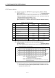
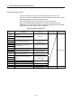
Details of the request register
No. Function Bit device Request register
1 PLC ready flag M2000 D704
2 Speed switching point specified flag M2040 D705
3 All axes servo ON command M2042 D706
4
Real mode/virtual mode switching
request (SV22)
M2043 D707
5
JOG operation simultaneous start
command
M2048 D708
6 Manual pulse generator 1 enable flag M2051 D755
7 Manual pulse generator 2 enable flag M2052 D756
8 Manual pulse generator 3 enable flag M2053 D757
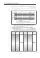
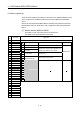
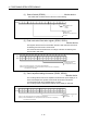
(2) JOG operation simultaneous start axis setting registers
(D710 to D713) .…............................................... Command device
(a) These registers set the virtual servomotor axis No. and direction which start
simultaneously the JOG operation.
b15 b14 b13 b12 b11 b10 b9 b8 b7 b6 b5 b4 b3 b2 b1 b0
Axis 16 Axis 15 Axis 14 Axis 13 Axis 12 Axis 11 Axis 10 Axis 9 Axis 8 Axis 7 Axis 6 Axis 5 Axis 4 Axis 3 Axis 2 Axis 1
Axis 32 Axis 31 Axis 30 Axis 29 Axis 28 Axis 27 Axis 26 Axis 25 Axis 24 Axis 23 Axis 22 Axis 21 Axis 20 Axis 19 Axis 18 Axis 17
Axis 16 Axis 15 Axis 14 Axis 13 Axis 12 Axis 11 Axis 10 Axis 9 Axis 8 Axis 7 Axis 6 Axis 5 Axis 4 Axis 3 Axis 2 Axis 1
Axis 32 Axis 31 Axis 30 Axis 29 Axis 28 Axis 27 Axis 26 Axis 25 Axis 24 Axis 23 Axis 22 Axis 21 Axis 20 Axis 19 Axis 18 Axis 17
Forward
rotation
JOG
Reverse
rotation
JOG
D710
D711
D712
D713
(Note-1) : Make JOG operation simultaneous start axis setting with 1/0.
1 : Simultaneous start execution
0 : Simultaneous start not
execution
(Note-2) : The range of axis No.1 to 8 is valid in the Q172DCPU.
(Note-3) : Refer to APPENDIX 2.1 for the expression method of axis No. corresponding
to the each bit of word data.
(b) Refer to Section 6.21.3 of the "Q173DCPU/Q172DCPU Motion controller
(SV13/SV22) Programming Manual (REAL MODE)" for details of the JOG
operation simultaneous start.