
Instruction manual


3 - 61
3 POSITIONING DEDICATED SIGNALS
(a) Servo amplifier mounting status
1) Mounting status
• Mounted ..…..... The servo amplifier is normal. (Communication with
the servo amplifier is normal.)
• Not mounted .... The servo amplifier is not mounted.
The servo amplifier power is off.
Normal communication with the servo amplifier is
not possible due to a connecting cable fault, etc.
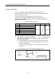
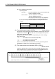
2) The system settings and servo amplifier mounting status are shown
below.
Servo amplifier
System Settings
Mounted Not mounted
Used (axis No. setting) 1 is stored 0 is stored
Unused 0 is stored
(4) Connect/disconnect (status) (SD508) ...................... Monitor device
This signal is used to temporarily suspend SSCNET communication while servo
amplifiers and/or SSCNET
cables after Axis 1 are exchanged with the power
supply ON in a Multiple CPU system.
SD508 stores the command status for "accept waiting" or "execute waiting"
during this process.
• 0 ………… Connect/disconnect command accept waiting
• -1 ……….. Connect/disconnect execute waiting
• -2 ………... Connect/disconnect executing
Refer to the "Q173DCPU/Q172DCPU Motion controller programming Manual
(COMMON)" for details of the connect/disconnect function.
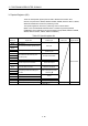
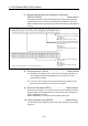
(5) Test mode request error information (SD510, SD511)
........... Monitor device
If there are operating axis at a test mode request using MT Developer, a test
mode request error occurs, the test mode request error flag (SM510) turns on,
and the during operation/stop data of the each axis are stored.
b15 b14 b13 b12 b11 b10 b9 b8 b7 b6 b5 b4 b3 b2 b1 b0
Axis 16 Axis 15 Axis 14 Axis 13 Axis 12 Axis 11 Axis 10 Axis 9 Axis 8 Axis 7 Axis 6 Axis 5 Axis 4 Axis 3 Axis 2 Axis 1
Axis 32 Axis 31 Axis 30 Axis 29 Axis 28 Axis 27 Axis 26 Axis 25 Axis 24 Axis 23 Axis 22 Axis 21 Axis 20 Axis 19 Axis 18 Axis 17
Stores the during operation/stop
data of each axis
SD510
SD511
(Note): The range of axis No.1 to 8 is valid in the Q172DCPU.
0 : During stop
1 : During operation