
Instruction manual

3 - 18
3 POSITIONING DEDICATED SIGNALS
(15) DOG/CHANGE signal (M2414+20n)
(Note-1)
..................Status signal
(a) This signal turns on/off by the proximity dog input (DOG) of the
Q172DLX/servo amplifier at the home position return.
This signal turns on/off by the speed/position switching input (CHANGE) of
the Q172DLX at the speed/position switching control.
(There is no CHANGE signal in the servo amplifier.)
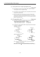
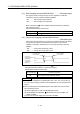
(b) When using the Q172DLX, "Normally open contact input" and "Normally
closed contact input" of the system setting can be selected.
The state of the speed/position switching input (CHANGE) when the
CHANGE signal is ON/OFF is shown below.
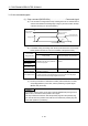
1) Q172DLX use
(Note-2)
DOG/CHANGE signal : ON
Q172DLX
DOG/CHANGE
DOG/CHANGE
COM
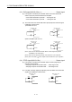
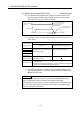
DOG/CHANGE signal : OFF
Q172DLX
DOG/CHANGE
DOG/CHANGE
COM
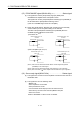
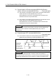
2) Servo amplifier input use
(Note-3)
DOG/CHANGE signal : ON
DOG/CHANGE
DI3
DICOM
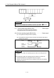
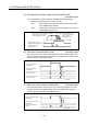
DOG/CHANGE signal : OFF
DOG/CHANGE
DI3
DICOM
MR-J3- B MR-J3- B
(Note-1): Refer to the "Q173DCPU/Q172DCPU Motion controller Programming Manual
(COMMON)" for an external signal.
(Note-2): Refer to the "Q173DCPU/Q172DCPU User’s Manual" for a pin configuration.
(Note-3): Refer to the "MR-J3-
B Servo Amplifier Instruction Manual" for a pin configuration.
(16) Servo ready signal (M2415+20n) ..............................Status signal
(a) This signal turns on when the servo amplifiers connected to each axis are in
the READY state.
(b) This signal turns off in the following cases.
• M2042 is off
• Servo amplifier is not mounted
• Servo parameter is not set
• It is received the forced stop input from an external source
• Servo OFF by the servo OFF command (M3215+20n) ON
• Servo error occurs
Refer to "APPENDIX 1.4 Servo errors" for details.