
Instruction manual

3 - 16
3 POSITIONING DEDICATED SIGNALS
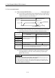
(11) Home position return complete signal (M2410+20n)
.......................Status signal
(a) This signal turns on when the home position return operation using the
servo program has been completed normally.
(b) This signal turns off at the positioning start, JOG operation start and manual
pulse generator operation start.
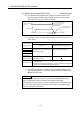
(c) If the home position return of proximity dog, dog cradle or stopper type
using the servo program is executed during this signal on, the "continuous
home position return start error (minor error: 115)" occurs and it cannot be
start the home position return.
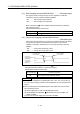
(12) FLS signal (M2411+20n)
(Note-1)
...................................Status signal
(a) This signal is controlled by the ON/OFF state for the upper stroke limit
switch input (FLS) of the Q172DLX/servo amplifier.
• Upper stroke limit switch input OFF ...... FLS signal: ON
• Upper stroke limit switch input ON ........ FLS signal: OFF
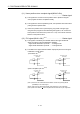
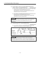
(b) The state for the upper stroke limit switch input (FLS) when the FLS signal
is ON/OFF is shown below.
1) Q172DLX use
(Note-2)
FLS signal : ON FLS signal : OFF
Q172DLX Q172DLX
FLS
FLS
COM
FLS
FLS
COM
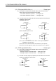
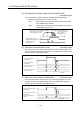
2) Servo amplifier input use
(Note-3)
FLS signal : ON FLS signal : OFF
FLS
DI1
DICOM
FLS
DI1
DICOM
MR-J3- B
MR-J3- B
(Note-1): Refer to the "Q173DCPU/Q172DCPU Motion controller Programming Manual
(COMMON)" for an external signal.
(Note-2): Refer to the "Q173DCPU/Q172DCPU User’s Manual" for a pin configuration.
(Note-3): Refer to the "MR-J3-
B Servo Amplifier Instruction Manual" for a pin configuration.