
Instruction manual


3 - 2
3 POSITIONING DEDICATED SIGNALS
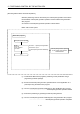
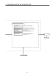
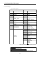
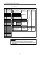
The positioning dedicated devices are shown below.
It indicates the device refresh cycle of the Motion CPU for status signal with the
positioning control, and the device fetch cycle of the Motion CPU for command signal
with the positioning control.
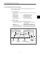
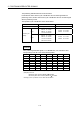
The operation cycle of the Motion CPU is shown below.
Item Q173DCPU Q172DCPU
Number of control axes Up to 32 axes Up to 8 axes
SV13
0.44ms/ 1 to 6 axes
0.88ms/ 7 to 18 axes
1.77ms/ 19 to 32 axes
0.44ms/ 1 to 6 axes
0.88ms/ 7 to 8 axes
Operation cycle
(Default)
SV22
0.44ms/ 1 to 4 axes
0.88ms/ 5 to 12 axes
1.77ms/ 13 to 28 axes
3.55ms/ 29 to 32 axes
0.44ms/ 1 to 4 axes
0.88ms/ 5 to 8 axes
REMARK
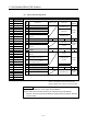
In the positioning dedicated signals, "n" in "M3200+20n", etc. indicates a value
corresponding to axis No. such as the following tables.
Axis No. n Axis No. n Axis No. n Axis No. n
1 0 9 8 17 16 25 24
2 1 10 9 18 17 26 25
3 2 11 10 19 18 27 26
4 3 12 11 20 19 28 27
5 4 13 12 21 20 29 28
6 5 14 13 22 21 30 29
7 6 15 14 23 22 31 30
8 7 16 15 24 23 32 31
• Calculate as follows for the device No. corresponding to each axis.
(Example) For axis 32
M3200+20n (Stop command)=M3200+20
31=M3820
M3215+20n (Servo OFF command)=M3215+20
31=M3835
• The range (n=0 to 7) of axis No.1 to 8 is valid in the Q172DCPU.